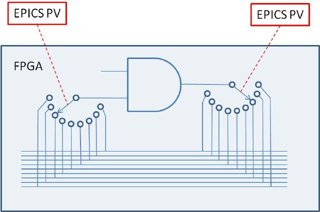
The name softGlue is intended to suggest glue electronics implemented by software, where glue electronics means those little bits of digital circuitry needed to connect two or more larger pieces of digital electronics into a working whole.
softGlue does this by loading an IndustryPack FPGA-based digital I/O module with a predefined collection of circuit elements (logic gates, counters, flip-flops, etc.), whose inputs and outputs are connected to switches controlled by EPICS PV's. softGlue provides a user interface for controlling those switches, allowing inputs and outputs to be marked with user-specified names, and connecting or driving inputs and outputs according to those names.
Here's the underlying idea, schematically:
To use softGlue, you must have the following hardware and software:
SoftGlue 2.x is intended to be useable with any IP_EP200-series module, but the databases and MEDM displays supplied in this version are for the IP_EP201, and other modules in the series have not yet been tested. The differences between modules are in the numbers of I/O bits, and the pinout.
To use an earlier version, see "Building softGlue" below.
This tool is needed to build some softGlue databases.
SoftGlue versions 2.1 and lower also require the EPICS calc module. Some of the databases, displays, and examples presume the availability of other synApps modules, such as calc, busy, and std, but these are not needed for any essential feature of softGlue.
You do not need to be able to program the IP-EP20x module. In the default implementation, the FPGA content is programmed automatically into the module at IOC-boot time, via the IP bus. A text file is included with softGlue for this purpose. softGlue attempts to load the FPGA on every IOC boot, but the load succeeds only on a cold boot. A warm boot leaves previously loaded content in place.
If you have a copy of Altera's "Quartus" software, you can load your own custom FPGA content into the module, and use softGlue to talk to it. softGlue was designed with this use in mind, though we don't yet have documentation on how it's done.
Here are a few examples of the sorts of things that can be accomplished with softGlue and EPICS:
Earlier versions of softGlue implented many components with both
inverting and noninverting outputs. Beginning with 2.0, signal inversion is
accomplished by appending '*' to a signal name, and this removes
the need to implement inverted outputs. Unfortunately, this means that softGlue
PV values saved from an earlier version of softGlue will not restore correctly
in softGlue 2.x. The functionality of the circuit will certainly still be
achievable, but signal names have changed, and the circuit will have to be
re-engineered.
In addition to the above listed components, softGlue 2.x includes shift registers, up/down counters, and quadrature decoders in separate FPGA packages. Currently, we don't have the capability of loading more than one FPGA-content file (the IP-EP20x FPGA does not support this), but we can combine the standard softGlue FPGA content with any one add-on package, and load that. Thus, there's a clear path to standard softGlue plus application-specific FPGA content and support. softGlue databases and MEDM-display files are engineered to simplify the development of support for add-on packages.
Unlike most other synApps modules, however, softGlue publishes the text files needed to boot an IOC in itsdbdirectory (as an EPICS module really should, I suppose — most synApps modules are nonstandard in this respect), rather than in thesoftGlueApp/Dbdirectory.
svn export https://subversion.xray.aps.anl.gov/synApps/softGlue/tags/R2-2 softGlue-2-2
softGlue/configure/RELEASE, to specify the paths to EPICS_BASE, ASYN, and
IPAC.
softGlueApp/src/drvIP_EP201.c to change the definition of the macro,
DO_IPMODULE_CHECK, like so: #define DO_IPMODULE_CHECK 0
make in the top-level directory, using the same make
executable used to build EPICS base.
The build will issue a warning that it can't expand all macros
in substitution files. This is not an error; unexpanded macros are intended
to be defined at boot time. (Note that version 1-4 of msi
returns an error, which causes the softGlue build to fail, after writing a
database file that contains unexpanded macros.)
configure/RELEASE
RELEASE file to define the following names:
SOFTGLUE=<path to the softGlue module>

			ASYN=<path to the asyn module>

			IPAC=<path to the ipac module>

			BUSY=<path to the busy module>
BUSYis an optional add-on for you to use with softGlue. If the busy module is available, you can arrange for EPICS database processing to wait for a signal from softGlue hardware before declaring itself to be finished. ThesoftGlue_convenience.dbdatabase loads busy records for this purpose, and thesoftGlueConvenience.adldisplay file contains menu items to display the records. Nothing else in softGlue depends on the busy module.
xxxApp/src
Makefile or a *Include.dbd file so that the file
softGlueSupport.dbd is included in the .dbd file the
IOC loads at boot time. You'll also need files from asyn, ipac, and busy,
if you're not already including them.For a Makefile:
iocxxx_DBD_vxWorks += softGlueSupport.dbd drvIpac.dbd asyn.dbd busySupport.dbdFor the .dbd file that will be loaded into a vxWorks IOC:
include "softGlueSupport.dbd"

				include "drvIpac.dbd"

				include "asyn.dbd"

				include "busySupport.dbd"
Makefile so that the IOC executable is linked with the
softGlue library. You'll also need libraries from the asyn, ipac,
and busy modules. The order in which libraries are named is sometimes
important.
Example:
xxx_LIBS_vxWorks += asyn Ipac softGlue busy
iocBoot/iocxxx
softGlue/iocBoot/iocSoftGlue/softGlue.cmd to your IOC directory,
which I'll call iocBoot/iocxxx, and edit the
dbLoadRecords() commands in your copy of softGlue.cmd to
define the macro P, so that it's unique to your IOC.
If you'll have more than one IP_EP20x module in an IOC, you'll also need to maintain separate definitions for the macro,H, for asyn port names associated with the modules, and for the macroREADEVENT. Port names are supplied as arguments to the functionsinitIP_EP200(),initIP_EP201(), and initIP_EP201SingleRegisterPort(), and they are supplied as the macro definitionsPORT,PORT1,PORT2, andPORT3indbLoadRecords()commands.
If you specify the same value of READEVENT for N instances of softGlue
in a single IOC, the software will still work, but it will use N times the CPU cycles,
as each instance will post read events that will cause all other instances to read
from the hardware.
st.cmd, before the call to
iocInit().
< softGlue.cmd
save_restore.cmd:
set_requestfile_path(softglue, "softGlueApp/Db")
Careful! the firstsoftgluemust be all lowercase, because this is how the path variable is defined incdCommands.
auto_settings.req (or whatever you've
named the file used to save/restore PV's of arbitrary type):
file softGlue_settings.req P=$(P) H=softGlue:
where the macros P, and H agree with those in
softGlue.cmd.
xxxApp/op/adl
softGlueMenu.adl display with the macros P, and
H, as defined in iocBoot/iocxxx/softGlue.cmd.
The file softGlueApp/op/adl/softGlueTop.adl contains an example button.
If you figure out how to use softGlue with some other display manager, please tell us about it, so we can include your work in the next version of softGlue. The MEDM-display files included in softGlue make heavy use of MEDM'scomposite file, and I don't know the extent to which a comparable feature exists in other display managers. softGlue's use ofcomposite fileis purely a display-development convenience.
setenv EPICS_DISPLAY_PATH $EPICS_DISPLAY_PATH':'$SOFTGLUE/softGlueApp/op/adl
cd <applicationTop>
make rebuild
initIP_EP200_FPGA(ushort carrier, ushort slot, char *filename)
   carrier:  IP-carrier number (numbering begins at 0)
   slot:     IP-slot number (numbering begins at 0)
   filename: Name of the FPGA-content hex file to load into the FPGA.

Example:
   initIP_EP200_FPGA(0, 2, "$(SOFTGLUE)/softGlueApp/Db/SoftGlue_2_2.hex")

Write content to the FPGA.  This command will fail if the FPGA already has
content loaded, as it will after a soft reboot.  When the command fails for this
reason, the already loaded FPGA content will be left as it was, with no ill
effect.  To load new FPGA content, you must power cycle the ioc.
int initIP_EP200(ushort carrier, ushort slot, char *portName1,
    char *portName2, char *portName3, int sopcBase)
    carrier:   IP-carrier number (numbering begins at 0)
    slot:      IP-slot number (numbering begins at 0)
    portName1: Name of asyn port for component at sopcBase
    portName2: Name of asyn port for component at sopcBase+0x10
    portName3: Name of asyn port for component at sopcBase+0x20
    sopcBase:  must agree with FPGA content (0x800000)

Example:
    initIP_EP200(0, 2, "SGIO_1", "SGIO_2", "SGIO_3", 0x800000)

Initialize basic field I/O
int initIP_EP200_Int(ushort carrier, ushort slot, int intVectorBase,
        int risingMaskMS, int risingMaskLS, int fallingMaskMS,
        int fallingMaskLS)
    carrier:       IP-carrier number (numbering begins at 0)
    slot:          IP-slot number (numbering begins at 0)
    intVectorBase: must agree with the FPGA content loaded (0x90 for softGlue
                   2.1 and higher; 0x80 for softGlue 2.0 and lower).  softGlue
                   uses three vectors, for example, 0x90, 0x91, 0x92.
    risingMaskMS:  interrupt on 0->1 for I/O pins 33-48
    risingMaskLS:  interrupt on 0->1 for I/O pins 1-32
    fallingMaskMS: interrupt on 1->0 for I/O pins 33-48
    fallingMaskLS: interrupt on 1->0 for I/O pins 1-32

Example:
    initIP_EP200_Int(0, 2, 0x90, 0x0, 0x0, 0x0, 0x0)

Initialize field-I/O interrupt support
Note that interrupt vectors are hardwired in the supplied FPGA content. Each IP-EP20x module uses three vectors (0x90, 0x91, 0x92), one for each set of 16 I/O bits. Depending on the interrupt-service mechanism supported by the operating system, multiple IP-EP20x boards may or may not all be able to generate interrupts. For PowerPC processors, interrupt-service routines (ISRs) are chained, so multiple IP-EP20x modules can all generate interrupts. But if the operating system doesn't permit multiple ISRs attached to a single interrupt vector, then only one IP-EP20x board will be able to generate interrupts.See "Field I/O Interrupt support", in the "User's Manual" section, for a description of the
softGlueFieldIO_Intxx.adlMEDM-display file by which interrupt generation can be controlled by the end user.
int initIP_EP200_IO(ushort carrier, ushort slot, ushort moduleType,
        ushort dataDir)
    carrier:    IP-carrier number (numbering begins at 0)
    slot:       IP-slot number (numbering begins at 0)
    moduleType: one of [201, 202, 203, 204]
    dataDir:    Bit mask, in which only the first 9 bits are significant.  The
                meaning of each bit depends on moduleType, as shown in the
                table below.  If a bit is set, the corresponding field I/O pins
                are outputs.  Note that for the 202 and 204 modules, all I/O
                is differential, and I/O pin N is paired with pin N+1.  For the
                203 module, pins 25/26 through 47/48 are differential pairs.
Correspondence between dataDir bits (0-8) and I/O pins (1-48)
| dataDir bit | 201 | 202 or 204 | 203 |
|---|---|---|---|
| bit 0 | pins 1-8 | pins 1, 3,25,27 | pins 25,27 |
| bit 1 | pins 9-16 | pins 5, 7,29,31 | pins 29,31 |
| bit 2 | pins 17-24 | pins 9,11,33,35 | pins 33,35 |
| bit 3 | pins 25-32 | pins 13,15,37,39 | pins 37,39 |
| bit 4 | pins 33-40 | pins 17,19,41,43 | pins 41,43 |
| bit 5 | pins 41-48 | pins 21,23,45,47 | pins 45,47 |
| bit 6 | x | x | pins 1-8 |
| bit 7 | x | x | pins 9-16 |
| bit 8 | x | x | pins 17-24 |
    Examples:
    1. For the IP-EP201, moduleType is 201, and dataDir == 0x3c would mean
       that I/O bits 17-48 are outputs.
    2. For the IP-EP202 or IP-EP204, moduleType is 202 or 204, and dataDir == 0x13
       would mean that I/O bits 1,3,25,27, 5,7,29,31, 17,19,41,43 are outputs.
    3. For the IP-EP203, moduleType is 203, and dataDir == 0x??? would mean
       that I/O bits 1-8, 25,27, 29,31, 33,35, 45,47 are outputs.
Example:
initIP_EP200_IO(0, 2, 201, 0x3c)
Set field-I/O data direction
int initIP_EP201(char *portName, ushort carrier, ushort slot,
        int msecPoll, int dataDir, int sopcOffset, int interruptVector,
        int risingMask, int fallingMask)
    portName: Name of asyn port for component at sopcOffset
    carrier:         IP-carrier number (numbering begins at 0)
    slot:            IP-slot number (numbering begins at 0)
    msecPoll:        Time interval between driver polls of field I/O bits
    dataDir:         Data direction for I/O bits, explained below.
    sopcOffset:      SOPC offset (must be as in example below).
    interruptVector: Must agree with the FPGA content loaded (0x90, 0x91,
                     0x92 for softGlue 2.1 and higher; 0x80, 0x81, 0x82 for
                     softGlue 2.0 and lower).
    risingMask:      16-bit mask: if a bit is 1, the corresponding I/O bit will
                     generate an interrupt when its value goes from 0 to 1.
                     Bit 0 corresponds to field I/O pin 1, bit 1 to pin 2, etc.
    fallingMask:     Similar to risingMask, but for 1-to-0 transitions.

                     Note that the user can overwrite risingMask and
                     fallingMask at run time, with menu selections, and
                     probably has those selections autosaved.

    dataDir is a bit mask in which only bits 0 and 8 are significant.
         for sopcOffset 0x800000
             If bit 0 of dataDir is set, I/O bits 1-8 are outputs.
             If bit 8 of dataDir is set, I/O bits 9-16 are outputs.
         for sopcOffset 0x800010
             If bit 0 of dataDir is set, I/O bits 17-24 are outputs.
             If bit 8 of dataDir is set, I/O bits 25-32 are outputs.
         for sopcOffset 0x800020
             If bit 0 of dataDir is set, I/O bits 33-40 are outputs.
             If bit 8 of dataDir is set, I/O bits 41-48 are outputs.

Example:
    initIP_EP201("SGIO_1",0,2,1000000,0x101,0x800000,0x90,0x00,0x00)
    initIP_EP201("SGIO_2",0,2,1000000,0x101,0x800010,0x91,0x00,0x00)
    initIP_EP201("SGIO_3",0,2,1000000,0x101,0x800020,0x92,0x00,0x00)
Note that interrupt vectors currently are hardwired in the supplied FPGA
content. Thus, if you want to use two or more IP_EP20x modules, only one may be
permitted to generate interrupts. Interrupt generation is entirely an end-user
choice, and it occurs only for the purpose of causing some EPICS record to
process on the change of state of a softGlue field I/O signal. See "Field I/O
Interrupt support" below for a description of the
softGlueFieldIO_Intxx.adl MEDM-display file by which interrupt
generation is controlled.
initIP_EP201SingleRegisterPort(char *portName, ushort carrier, ushort slot)
Initialize softGlue signal-name support.
Example:
initIP_EP201SingleRegisterPort("SOFTGLUE", 0, 2)
Most of the essential user-interface information — how to connect signals, what the display elements mean, etc. — is contained in the descriptions of the "User Menu" and "AND" sections below. The remaining sections are mostly for completeness, though some circuit elements do require further explanation, and the counter sections introduce new display elements for registers containing decimal numbers.
We're going to have a little trouble with the meanings of "input" and "output", because they imply a viewpoint, and because we're going to be taking three different viewpoints: those of EPICS records, circuit elements, and field-wiring connectors. Usually, in EPICS, we think of an output as something to which an EPICS record can write, but that definition would be awkward here, because it would eventually require us, for example, to refer to the output of an AND gate as an "input". You just can't discuss digital circuitry intelligibly from that viewpoint.
Therefore, in this documentation, "input" and "output" will normally be from the viewpoint of one of the circuit elements we'll be wiring. Field I/O will be an exception, because it's most conveniently discussed from the viewpoint of the field-wiring connector.
User Menu
softGlueMenu.adl is the top softGlue display, which serves mostly to call up other
displays. The menu labelled READ PERIOD specifies the period at which the values of
all signals are sampled for display to the user.
Most softGlue displays are not interrupt driven. (That would be a disaster, because inevitably some signals will change state at high frequency.) So, the states of inputs and outputs must be sampled periodically, for display to the user.We've found that it's confusing for users if the poll period is greater than around 1 second. We've also found that polling everything at .1 second uses only a few percent of an MVME2700 CPU.
AND
On the left of the AND gate are the inputs, each comprised of a blue "= button", a yellow text-entry field, a number, and what's intended to look like a red LED. On the right are essentially the same things in reverse order, but an output's text-entry field is a different color. The text-entry fields are used to connect signals together, and the color difference is intended to remind you of the only rule governing signal connections: if you connect two or more outputs together, those outputs won't work.
softGlue outputs are engineered to ensure that you can't break anything by connecting outputs together, but the circuit won't be useful until you fix the error, because the states of outputs connected together are undefined. Currently, softGlue doesn't signal this error by putting offenders into an alarm state.
The yellow text-entry box controls an input. You have three options:
This directly writes a logic value (optionally, a pulse) to the input.
softGlue will parse everything that looks numberish, and convert to a floating point value. This sets the input to a logic value: 0 if the nearest integer to the converted value is zero, 1 if it's not.
Allowing floats, and extra characters after the number makes it easier to drive softGlue inputs with calcout records, replies from serial devices, etc.
The strings "0!" and "1!" (possibly followed by other ignored characters) direct softGlue to
write a pair of logic values: "0!" writes "0" followed immediately by "1"; "1!" writes "1" followed
immediately by "0". The time interval between writes is system dependent, and not at all
guaranteed, but it should be much smaller than the interval you could achieve from separate writes.
On an MVME2700, I measure around 6 μs.
This names the signal, and connects it to all other signals with the same name (or with the
same name followed by '*', as described below). Case is significant in comparing
signal names.
Note that a "signal", as the word is used in this documentation, is a named connection between softGlue circuit elements. It might be more intuitive to think of a "signal" as a wire, to avoid confusing it with, say, field I/O.
Note, if you're using more than one IP-EP20x module, that you can't connect signals implemented in different IP-EP20x modules using their text-entry boxes. To accomplish this, you must connect the signals to field I/O and make a physical connection.
If you want to use the inverted value of a signal for input to some component, append
'*' to the signal name. This doesn't change the signal that the input is
connected to, but just tells softGlue to run the signal through an inverter before applying it
to the input. Note that output signal names may not end with '*'.
In MEDM, you can use Drag-And-Drop to connect a named signal to some other signal. When you drop, MEDM will put the PV name of the signal you dragged from. When you press <Enter>, softGlue's device support will write the signal name of the source PV to the destination PV.
In caQtDM, you can select the text of a signal name, and use Copy/Paste (^C/^V) to copy the signal name from one text-entry box to another.
Whatever option you choose, you can define at most fifteen different signal names. When you try
to define the 16th name, softGlue will erase whatever you wrote, and put the record into the
"INVALID" alarm state. (But note, for example, that reset and reset* are
not different signal names, because the trailing '*' is not regarded as part of the
name; it merely describes how the signal should be used.)
Text-entry boxes for output signals won't accept names beginning with a number, or ending with
'*'. (softGlue will simply strip the offending characters, and leave the rest.)
A signal name beginning with a number can only be a direct-write command; it cannot connect things together, because the leading number would be misinterpreted by input-signal-name parsing as a direct-write command. Output-signal names ending with '*' are logically sensible, but are not permitted; this simplifies the implementation of '*' appended to input-signal names.
A signal's blue "= button" is used to find all other signals to which the signal is connected. While a signal's "= button" is pressed, input signals connected to it are bordered in green, and output signals connected to it are bordered in orange. If you ever see two or more orange borders at the same time, you have outputs connected together, and your circuit won't work.
The little red and black filled circles (LED's), and the numbers next to them, display the states
of their signals. These display elements are updated at the period specified in the
softGlueMenu.adl display. If you want the EPICS PV name corresponding to a signal's
logic value, this is the PV name to use.
For completeness, here's the truth table for an AND gate:
| input1 | input2 | output | |
|---|---|---|---|
| 0 | x | 0 | |
| x | 0 | 0 | |
| 1 | 1 | 1 |
'x' means "either 0 or 1".
OR
| input1 | input2 | output | |
|---|---|---|---|
| 0 | 0 | 0 | |
| 1 | x | 1 | |
| x | 1 | 1 |
BUFFER
The purpose of the buffer element is to permit EPICS to drive several softGlue inputs by writing to a single PV, without using up a more valuable circuit element, such as the XOR gate below.
INVERTING BUFFER
There is no inverting buffer - or any other inverting gate - in softGlue. Signal inversion is accomplished by appending '*' to the name of a signal used as as input to any logic element, as demonstrated above for the buffer element. Note that '*' appended to the name of an output signal will be removed.
XOR
| input1 | input2 | output | |
|---|---|---|---|
| 0 | 0 | 0 | |
| 0 | 1 | 1 | |
| 1 | 0 | 1 | |
| 1 | 1 | 0 |
D FlipFlop
The input signal labelled ">" is the "clock" input. Unlike other signals, clock inputs are edge sensitive. All clock inputs in softGlue act on the rising edge of the input signal.
The open circle ("bubble") in the SET and CLEAR inputs' signal paths indicate
that these signals are inverted before being used. Thus, applying '0' to the CLEAR input causes
the output to be "cleared" (given the value 0).
| SET | CLEAR | D | > (clock) | Q | |
|---|---|---|---|---|---|
| 0 | 0 | x | x | undefined | |
| 0 | 1 | x | x | 1 | |
| 1 | 0 | x | x | 0 | |
| 1 | 1 | any | rising edge | DBEFORE (value D had immediately before the rising edge of the clock signal) |
2-Input Multiplexer
When SEL==0, OUT=IN0. When SEL==1, OUT=IN1.
2-Output Demultiplexer
When SEL==0, OUT0=IN, and OUT1 is undefined (currently
0). When SEL==1, OUT1=IN, and OUT0 is undefined (currently
0).
Up Counter (32-bit Counter)
EN==1 enables the clock (">") input, whose rising edge increments the counter value.
Down Counter (32-bit Preset Counter)

EN==1 enables the clock (">") input, whose rising edge decrements the counter value.
When LOAD==1 the counter is loaded with the value applied to the PRESET
input. While LOAD==1, the counter does not count down. While LOAD==0 and
EN==1, a rising edge at the clock input decrements the counter. When the counter value
reaches 0, the output Q goes to 1; the next rising edge of the
clock returns Q to 0 (regardless of the states of EN and
LOAD).
32-bit Divide By N
EN==1 enables the clock (">") input. Every N'th
rising edge of the clock drives Q to 1. The next
rising edge returns Q to 0. This behavior produces the correct number of rising edges of
the output signal, but it does not guarantee the same number of falling edges.
Therefore, using an inverted copy of the output to clock downstream electronics
will in some cases have inconsistent results.
When N==0, the divide circuitry is bypassed, and the
clock is connected directly to Q. This is an error; the output
should still be gated by the EN signal.
In softGlue version 2.1 and earlier, the RESET signal doesn't do
anything. Beginning with softGlue 2.2, the RESET signal loads the
counter with N, so that Q will be driven to
1 after N rising edges of the clock.
RESET does not clear the output Q. If Q
is 1, it will be cleared on the first rising edge of the clock.
8 MHz internal clock
An 8 MHz clock derived from the IndustryPack clock is available to softGlue circuitry as a free standing output.
Field I/O
This display allows you to connect field I/O signals to each other and to softGlue circuits. Note that a "Field Input Bit" looks like and behaves as a softGlue output, because what you're actually controlling is the output of a buffer driven by the field-input signal. Similarly, a "Field Output Bit" looks like and behaves as a softGlue input, because you're actually controlling the input of a buffer that drives the field-output signal.
The signals in this display are the field inputs or outputs connected to pins 1-16, 17-32, or 33-48 on the IP-EP201's ribbon connector. The IP-EP201 board supports 48 I/O bits, and permits them to be set for input or output in groups of 8.
"POLL TIME (MS)" specifies the period at which softGlue reads the I/O ports for user-display purposes, and for executing the EPICS link associated with non-interrupt-enabled I/O bits (see next section). If an I/O bit has changed value since the last read, softGlue processes the display record associated with that bit, so the user will see the new value. If an I/O bit is enabled to generate interrupts, as described in the next section, the bit will be read immediately by the interrupt handler, so "POLL TIME" will not matter for that bit.
Note: If you have a field input connected to an FPGA component, the component will react to a change in the input value within nanoseconds. I/O polling is not involved at all in the logic connection.
You can change the "CONNECTOR #" strings in this display — for example, to support a custom signal-breakout module, or to give the I/O signals application-specific names. The strings are defined insoftGlueApp/Db/softGlue_FPGAContent.substitutions, as the macroIOPINsupplied tosoftGlue_FieldOutput.dbandsoftGlue_FieldInput.db. In softGlue 2.3.1, field I/O displays leave room for longer strings, and there is a an autosave-request file for these PVs.
During a VME power cycle, and during a VME reset, field outputs are first put into a high impedance state, then are driven to ground, and finally are driven to values controlled by the user circuit. If user-circuit field-outputs are autosaved, they will be restored during the boot; otherwise, they will default to logic 1 (+5V for TTL).
During a soft reboot (that is, when the vxWorks "reboot" command is given in the ioc console), field outputs will maintain their values.
Field I/O Interrupt support
Field-input lines supported by softGlue can generate interrupts on rising edges, falling edges, both, or neither. You control this by setting the "INTERRUPT ENABLE" menu to "Rising", "Falling", "Both", or "None", respectively. Field output lines can also generate interrupts: if a bit is designated as an output, the output is connected also to the input, and to the input's interrupt-generation circuitry.
Interrupts are throttled by softGlue's interrupt handler. If more than four interrupts have occurred and not been handled, softGlue will disable interrupts from the offending bit, by setting the bit's "INTERRUPT ENABLE" menu to "None", and it will direct your attention to the change by drawing a red box around the menu control. The box will be erased the next time the menu is written to.
The number of unhandled interrupts that triggers throttling is adjustable by modifying drvIP_EP201.c. You must change the definition ofMAX_IRQ, and you must also ensure that the asyn ring buffers for interrupt driven PV's is larger thanMAX_IRQ. (The default ring buffer size is 10. Asyn documentation describes how to change it.)
When an interrupt occurs, you can have the signal value written to an EPICS PV, by writing an EPICS link description into the purple box labelled "ON INTERRUPT, WRITE SIGNAL VALUE VIA THIS LINK", as shown for input 16 in the above screen shot.
For interrupts that may occur too closely spaced in time for softGlue's normal interrupt-response mechanism to handle reliably, see "Custom Interrupt Handlers", below.
In softGlue displays (and in most other synApps displays), standard EPICS links are displayed as purple text-entry boxes, in which you describe the link you want to make. For purposes here, an EPICS link description is the name of an EPICS PV, followed by one of the following link attributes:
| NPP | (default) write value, but do not cause processing. |
| PP | write value and cause processing (if the record containing the PV is "Process
Passive", which means that it's SCAN field has the value "Passive"). You should use this attribute unless you have some reason not to use it. |
| CA | write value and let the record containing the PV decide whether or not to process. |
EPICS will tack on the string " NMS". This alarm-propagation attribute is not something end users need to worry about.
For example, to cause a link to write effectively to the top input of the first AND gate
(whose PV name is xxx:softGlue:AND-1_IN1_Signal, you would write the following
into a purple box:
xxx:softGlue:AND-1_IN1_Signal PPIf you only write the PV name, EPICS will supply the link attribute
NPP, and your link
will write a value, but the value won't have any effect until the next time the record processes.
(For most PV's in softGlue, the value written by an NPP link won't even be displayed until the
record processes.)
Note: if the link writes to a PV in a different IOC, the specified link attribute will be ignored, and the attribute "CA" will be used instead.
Everything on one display, with the signal named "clock" highlighted so that all of its connections are evident. A signal name gets this treatment when the "= button" next to an input or output is pressed. Note that connections to inputs are bordered in green, and connections to outputs are bordered in orange.
This display shows everything in softGlue except interrupt support.
Convenience
This display controls two pulse generators implemented in EPICS, with links allowing them to write to a softGlue input (that is, to a yellow box), and, similarly, two clock generators implemented in EPICS. The display also has MEDM related-display callups for two busy records,
The use of EPICS links (the purple boxes in the above display) is described above in the section "About EPICS links", in the documentation of "Field I/O Interrupt support".
BusyRecord
This display controls the value, output link, and forward link of a busy record. In the anticipated use with softGlue, one would have some EPICS record outside of softGlue set the busy record to "Busy" (using a PP link), and arrange for a softGlue interrupt bit (see "Field I/O Interrupt support", above) to use its EPICS-output link to clear the busy record to "Done" (using a CA link).
The use of EPICS links (the purple boxes in the above display) is described above in the section "About EPICS links", in the documentation of "Field I/O Interrupt support".
It's important to set a busy record to "Busy" using a PP link, because the purpose of a busy record is to represent some external processing as EPICS processing. This allows EPICS' execution tracing to signal the completion of the processing. EPICS only traces processing started or propagated with a PP link.It's important to clear a busy record to "Done" with a CA link, because an EPICS PP link will decline to process any record that is already processing. The busy record is written so that a CA put will succeed in clearing it and causing its processing to appear done to EPICS.
32-bit Up/Down Counter
EN==1 enables the clock (">") input. CLEAR==1 sets
the current count and the output value Q to zero. When
UP/DOWN==1 the counter counts up. LOAD sets the
current count to PRESET
Quadrature Decoder
This circuit converts a pair of digital quadrature signals A, B
(for example, signals from an encoder) into a pair of STEP, DIR
signals. A and B are samples on rising edges of the
CLOCK signal. If either have changed since the last rising edge,
the travel direction implied by the change is output to DIR, and a
pulse is output to STEP. The pulse width is equal to the period of
the CLOCK signal, and the input frequency may not be greater than
half the clock frequency.
Shift Register
This circuit converts from parallel to serial, or from serial to parallel.
For parallel-to-serial conversion, a number is written into the
For serial-to-parallel conversion, the input
LOADVAL register, and loaded by a positive-going pulse to the
LOAD input. On each rising edge of the clock input
>, the loaded value is shifted toward the most significant bit,
and the most significant bit is output to the D is sampled on the
rising edge of the clock input, and that value is shifted into the least
significant bit of the register.
Whichever method you use, you may need to clear softGlue signal names before loading a circuit, because loading over an existing circuit could temporarily exceed the available number of signal names. (Alternatively, you could simply load twice, and be confident that the second load will succeed.)
If you have autosave R5-1 or higher, you can use configMenu to save and restore circuits. Here are the steps needed to implement a menu of softGlue circuits, and to give the user a GUI display for saving and restoring them. (In the following, SG is the name of this instance of configMenu. The files it loads and saves will be named "SG_<config Name>.cfg". For examples, the configMenu instance pictured above has files named "SG_clear.cfg", "SG_encoderTest.cfg", etc..)
- In the IOC's startup directory, create an autosave request file, which I'll call "SGMenu.req", with the following content:
	file configMenu.req P=$(P),CONFIG=$(CONFIG)

file softGlue_settings.req P=$(P),H=$(H)- Uncomment the following line in the IOC's copy of
softGlue.cmd:
dbLoadRecords("$(AUTOSAVE)/asApp/Db/configMenu.db","P=xxx:,CONFIG=SG")- Add the following line to
st.cmd:
create_manual_set("SGMenu.req","P=xxx:,CONFIG=SG")- Add an MEDM related-display entry to bring up the configMenu.adl display.
	label="SGMenu"

	name="configMenu.adl"

	args="P=xxx:,CONFIG=SG"
softGlue includes configMenu files (*.cfg) for standard example circuits in the iocBoot/iocSoftGlue directory. In actual use, these .cfg files would be placed in your application's iocBoot/iocxxx/autosave directory. For more information on configMenu, see the autosave documentation.
softGlueApp/op/burt/softGlue.snap can be
used to save all softGlue user modifiable PV's. For example, the following
command saves the state of softGlue to the file myCircuit.snap.
burtrb -f softGlue.req -DPREFIX=xxx:softGlue -o myCircuit.snap
No doubt your PREFIX will be different from mine, but it should be
- "
-f softGlue.req"- specifies that the request file
softGlue.reqshould be used to specify the EPICS PVs whose values are to be saved. This file contains lines like this: "PREFIX:AND-1_IN1_Signal", where "PREFIX" is to be replaced by text specific to your ioc.- "
-DPREFIX=xxx:softGlue"- specifies that
PREFIXis to be replaced byxxx:softGlue.- "
-o myCircuit.snap"- specifies that the saved PV names and values are to be written to the snapshot file "
myCircuit.snap".$(P)$(H)from your copy ofsoftGlue.cmd, minus the trailing ':' from $(H). BURT needs the ':' to separate "PREFIX" from the rest of the PV names it parses. If you defined H without a trailing ':', you'll need to make some adjustment to satisfy BURT.
The following commands restore the circuit:
burtwb -f clearAll.snap
burtwb -f myCircuit.snap
The first command is often needed because there is a limit to the number of signal names that softGlue will accept. If you neglect to clear all signals before restoring a circuit, the allowed number of signal names might be exceeded during the restore, if new signal names are defined before old signal names are deleted. (Alternatively, you could simply run the second command twice.)
To restore example circuits included in the softGlue module, or to
restore a snapshot file emailed to you by some other softGlue user, you will
need to edit the snapshot file to change PV names such as
"xxx:softGlue:AND-1_IN2_Signal" to PV names in your ioc, which
might look like "1ida:softGlue:AND-1_IN2_Signal".
The following circuits have been tested and saved in BURT snapshot files, and
as configMenu .cfg files, as described above (see Saving and Restoring
Circuits). The snapshot files can be found in
softGlueApp/op/burt; the .cfg files are in iocBoot/iocSoftGlue.
Negative-going pulses can be gated with an OR gate, by applying the signal to one input of the OR gate, and setting the other input to 0(1) to allow(deny) passage through the gate.
Files:
softGlueApp/op/burt/gatedScaler.snap or
			iocBoot/iocSoftGlue/gatedScaler.cfg
This circuit implements four counter channels, a time base to control
counting time, an overall gate, and additional circuitry to control
starting, stopping, and processing of the count-value records. Note
that the scaler is controlled by a busy record from the softGlue
convenience database, so that client software can discover when counting
is finished in the standard EPICS way. See
softGlueApp/op/burt/gatedScaler.txt for more details.
File: softGlueApp/op/burt/fourPulses.snap or
iocBoot/iocSoftGlue/fourPulses.cfg
This circuit produces four separate pulse signals, which start at
specified start-delay times after (the falling edge of) an initial start
pulse, and which last for specified pulse-length times. It uses four
DnCntr's to implement the start-delay times, and four DivByN's to
implement the pulse-length times. Times are specified as multiples of
the (125 ns) clock period (PRESET for the DnCntr's;
N for the DivByN's), and these numbers must be greater than
or equal to 1. The pulse sequence starts on the falling edge of the
signal BUF-1, written by a periodically scanned EPICS
record (one of the softGlue convenience clocks). One spare signal name
is available, however, so the pulse sequence could also be started by an
external signal.
Files: softGlueApp/op/burt/accelDecelGate.snap or
iocBoot/iocSoftGlue/accelDecelGate.cfg
(Non-softGlue support in
softGlueApp/op/burt/accelDecelGate_transform.sav.)
If you know the number of steps a stepper motor will move during its acceleration time, you
can easily arrange to deliver motor pulses to some external circuit only while the motor is
moving at constant speed. For a stepper motor controlled by the motor record, the number of
acceleration/deceleration steps, Na, can be calculated with the following
formula:
Na = ((VBAS+VELO)/2)*ACCL/MRES
where, VBAS, VELO, ACCL, and MRES are
motorRecord fields.
The number of constant-speed steps, Nc, is then
Nc = ((VALend - VALstart)/MRES) -
		2*Na
where VALend and VALstart are the final
and initial values of the motorRecord VAL field.
The following circuit accepts negative-going motor pulses at input signal 1, gates out
the first 11 (the value of DnCntr-1_PRESET), and from then on sends motor
pulses to output pin 17 until a total of 31 (the value of DnCntr-2_PRESET) have
been sent. The circuit is reset by writing "1!" (positive-going pulse) to the input of BUF-1.
The circuit includes some diagnostics, and a mechanism for testing:
UpCntr-1 counts all motor pulses; UpCntr-2 counts gated
motor pulses. Both counters are reset by the same signal that resets the gate circuit.
Down counter DnCntr-1, and flipflop DFF-1, together produce a gate
signal that is 0 after a reset, and that goes to 1 after DnCntr-1_PRESET motor
pulses. Down counter DnCntr-2, and flipflop DFF-2, together produce a
gate signal that is 1 after a reset, and that goes to 0 after DnCntr-2_PRESET motor
pulses. We load the number of acceleration steps into DnCntr-1_PRESET, and the
number of acceleration steps plus constant-speed steps into DnCntr-2_PRESET.
AND-1 combines the gate signals produced above into a signal that is 1 while
the motor is moving at constant speed.
AND-2 gates the negative-going motor pulses, using what
was described in the "Motor-pulse gate" example as a
positive-going-pulse gate, by inverting the "motor" signal before
applying it to the gate.
Note that the down counters are clocked by (rising edges of) "motor", to produce the
signal used to gate "motor*". This choice avoids a race condition between simultaneous
rising edges of "gateOut" and "motor". (This circuit gates negative-going motor pulses, so
another way to make the point is to say that the trailing edge of a motor pulse is used to
produce a gate that will be ready in plenty of time for the leading edge of the next motor
pulse.)
Calculations for the circuit are shown in the following screen capture of a transform record.
For more softGlue-circuit examples, see https://subversion.xray.aps.anl.gov/admin_bcdaext/softGlue_examples Currently, the following circuits are documented:
Getting clean electrical signals from the IP-EP201 out to field wiring requires some attention to detail. The signals have short rise times (on the order of a few ns), and the IP-EP201 pinout places 48 of them on adjacent ribbon-cable conductors, with a single ground conductor at one end of the ribbon. This combination pretty much guarantees problems with crosstalk and ringing.
Firstly, sharp-edged signals produce significant crosstalk between conductors, because the magnetic fields generated by signal currents vary rapidly enough during changes of state to induce significant voltages in nearby conductors. There is also the possibility of crosstalk from the fact that return currents of all signals share a single ground conductor. The shared-ground contribution is small, compared to the magnetic-field-induced contribution, but it could be significant in long (tens of feet) ribbon cables.
Secondly, sharp-edged signals require transmission-line termination to damp reflections at impedance mismatches. Otherwise downstream electronics will see ringing, as current sloshes back and forth through the cable, which can (if it exceeds the TTL noise margin) make each transition look like two or more. But the IP-EP201 has no termination, and its pinout results in 48 coupled transmissions lines, for which effective termination is probably not possible.
Nevertheless, it's possible to get clean signals to field wiring using the following strategy:
The APS BCDA group has produced three circuit boards that implement this strategy:
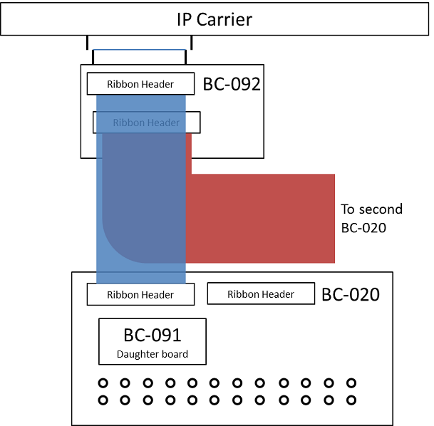
The BC-092 plugs directly into the IP carrier's 50-pin ribbon connector.
(Take care: the connector is not polarized. It's your job to plug it in the
right way.) A ribbon cable goes from the BC-092 to the H1 ribbon
header on the BC-020 board. (The H2 header is not used for
softGlue.) The BC-091 daughter board is plugged into the BC-020, and the I/O
direction is set, for groups of eight bits, with DIP jumpers on the BC-091.

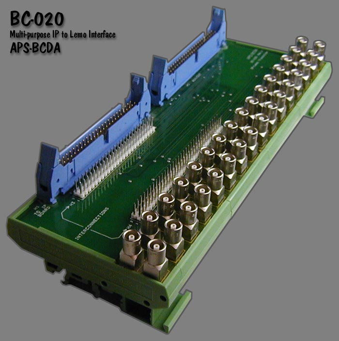
The BC-020 LEMO interface. With the EP-201 board, only the first 24 LEMO connectors are used. The BC-091 daughter board is plugged into the white headers at the center of the board.
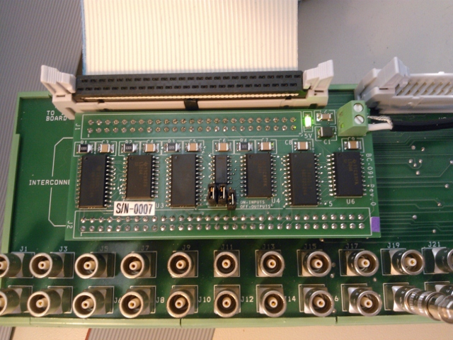
A BC-020 board with the BC-091 daughter board installed. Note the DIP jumpers near the center of the daughter board. With this setting, I/O pins 1-16 are inputs (jumper on), and pins 17-24 are outputs.
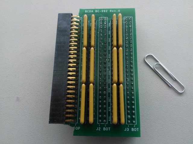
Closeup of the BC-092 board, with SIP resistor packs installed. Normally, 100-Ohm resistors are used, because this is the nominal impedance of many ribbon cables. Although the terminating resistors are useful only for outputs, they are usually installed for all I/O pins.
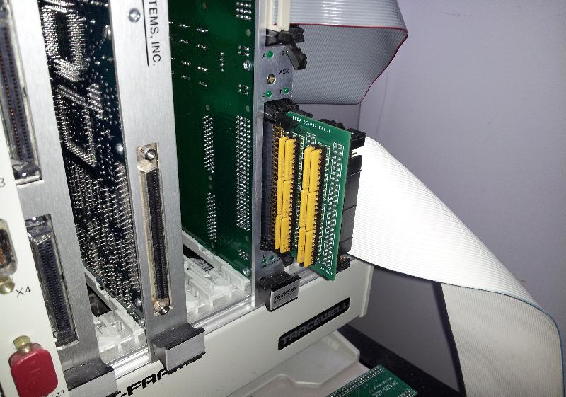
Closeup showing how to connect the BC-092 to the TEWS TVME-200 IP carrier.
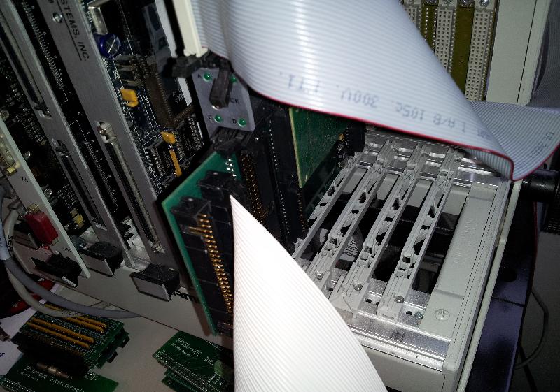
Closeup of the other side of the BC-092 board. The ribbon connector closest
to the IP carrier (the J2 connector) handles I/O pins 1-24.
This section not yet written.
This section not yet written.
For interrupts that may occur more closly spaced in time, you can write a custom interrupt-handler routine, and tell softGlue to call it at interrupt level whenever an enabled interrupt occurs. There is an example in the softGlueApp/src directory: sampleCustomInterruptHandler.c, which handles the following application requirement:
When an enabled interrupt occurs on a specified bit of a specified IP_EP20x board,
read a number from an array, write that number to the N register of a specified
softGlue DivByN component on that same IP_EP20x board, and increment the array index for the
next read.
sampleCustomInterruptHandler.c contains two functions:
sampleCustomInterruptPrepare()
sampleCustomInterruptRoutine(), and tells softGlue to call
sampleCustomInterruptRoutine() from its interrupt-service routine when a specified
interrupt occurs. The interrupt is specified by carrier and slot,
which specify the IP_EP20x board; sopcAddress, which specifies the address of one of
three I/O registers on the board; and mask, which specifies one or more bits of the
specified I/O register.
sampleCustomInterruptRoutine()
N register whose VME addresses were calculated by
sampleCustomInterruptPrepare(), and increments the array index.
Other files in softGlueApp/src that help implement sampleCustomInterruptHandler are
Makefile, which builds it, and softGlueSupport.dbd, which
contains the line registrar(sampleCustomInterruptRegistrar).
msi at build time to
produce the database file softGlue_FPGAContent.db. The database
file loads records matching most of the FPGA content that is loaded at cold-boot
time from SoftGlue_2_2.hex.
msi at build time to produce the database file
softGlue_FPGAContent_octupole.db. The database file loads records for the two 32-bit
shift registers in SoftGlue_2_2_Octupole_0_0.hex.
msi at build time to
produce the database file softGlue_FPGAContent_Encoder.db. The
database file loads records for the two 32-bit up/down counters in
SoftGlue_2_2_Encoder.hex.
msi at build time to
produce the database file softGlue_FPGAContent_s1ID_Vgate.db. The
database file loads records for the two 32-bit up/down counters in
SoftGlue_2_2_1ID_Vgate_0_1.hex.
msi at build time to
produce the database file softGlue_FPGAInt.db. The database file
loads records matching the field-I/O register components loaded into the FPGA.
These components control the field I/O registers which softGlue uses to connect
with external wiring. The file also loads records by which the user can control
the period at which the driver's poller thread wakes up to read any I/O bits
that have not been enabled to generate interrupts.
msi to produce partially
resolved databases loaded by dbLoadRecords().
In the rest of this display-file documentation, I'll give MEDM examples. For CSS-BOY examples, just substitute ".opi" for ".adl". For caQtDM, substitute ".ui".
The display of a softGlue circuit element is built in layers, from instances of softGlue_Input.adl and softGlue_Output.adl, which are included in softGlue_<element name>_bare.adl, which in turn is included in one of the user displays (for example, softGlueAll.adl, softGlue_AND.adl, etc.).
softGlueMenu.adl contains related-display menus for everything in softGlue.
softGlueTop.adl is an example of how softGlueMenu.adl can be called up.
softGlue's driver implements four asyn ports to connect EPICS records with registers implemented in the IP-EP20x module's FPGA. Three ports connect with "fieldIO_registerSet" components, which provide comprehensive control over digital I/O bits implemented in the module, including data direction (i.e., read or write), interrupt enable, and status. The fourth asyn port connects with "single 16-bit register" components, with which all softGlue signal connections are implemented.
The following is copied from drvIP-EP201.c:
    This driver cooperates with specific FPGA firmware loaded into the Acromag
    IP-EP201 (and probably other IP-EP200-series modules).  The loaded FPGA
    firmware includes Eric Norum's IndustryPack Bridge, which is an interface
    between the IndustryPack bus and the Altera FPGA's Avalon bus.  The
    IndustryPack Bridge does not define anything we can write to in the FPGA.
    It's job is to support additional firmware loaded into the FPGA.  The
    additional firmware defines registers that we can read and write, and it can
    take one of the two forms (sopc components) supported by this driver:

        1) fieldIO_registerSet component

           A set of seven 16-bit registers defined by 'fieldIO_registerSet'
           below.  This register set provides bit-level I/O direction and
           interrupt-generation support, and is intended primarily to
           implement field I/O registers.

        2) single 16-bit register component

           a single 16-bit register, which has no interrupt service or bit-level
           I/O direction.  This type of sopc component is just a plain 16-bit
           register, which can be written to or read.  This driver doesn't know
           or care what the register might be connected to inside the FPGA.

    Each fieldIO_registerSet component must be initialized by a separate call to
    initIP_EP201(), because the component's sopc address must be specified at
    init time, so that the interrupt-service routine associated with the
    component can use the sopc address.  Currently, each call to initIP_EP201()
    defines a new asyn port, connects an interrupt-service routine, creates a
    message queue, and launches a thread.

    Single 16-bit register components, on the other hand, need not have their
    sopc addresses known at init time, because they are not associated with an
    interrupt service routine.  As a consequence, many such single-register
    components can be served by a single asyn port.  Users of this port must
    specify the sopc address of the register they want to read or write in
    their asynUser structure. Records do this by including the address in the
    definition of the record's OUT or INP field.  For example, the ADDR macro in
    the following field definition should be set to the register's sopc address:
    field(OUT,"@asynMask($(PORT),$(ADDR),0x2f)")

    The addressing of sopc components requires some explanation.  When a
    component is loaded into the FPGA, it is given an sopc address, which is a
    number in one of two regions of the Avalon address space.  These regions of
    Avalon memory space are mapped by the IndustryPack Bridge to specific ranges
    of the IndustryPack module's IO and MEM spaces.  The IO and MEM spaces, in
    turn, are mapped by the IndustryPack carrier, and by the ipac-module
    software, to corresponding ranges in a VME address space.  The lowest
    address in the IndustryPack module's IO space is mapped to the VME A16
    address given by ipmBaseAddr(carrier, slot, ipac_addrIO), which I'll call
    IOBASE in the following table.  The lowest address in the IndustryPack
    module's MEM space is mapped to the VME A32 address given by
    ipmBaseAddr(carrier, slot, ipac_addrMem), which I'll call MEMBASE in the
    following table.  (The module's MEM space could also have been mapped to the
    VME A24 space.  This code doesn't know or care, because it just gets the VME
    address by making a function call to code provided by the ipac module.)

    Note that IOBASE and MEMBASE depend on the IndustryPack carrier and slot
    into which the IP-EP200 module has been placed.

    Avalon_address | IP_space  IP_address  | VME_space   VME_address
    (sopc address) |                       |
    ---------------|-----------------------|-----------------------------
    0x000000       | IO        0x000000    | A16         IOBASE+0x000000
    ...            | IO        ...         | A16         ...
    0x00007f       | IO        0x00007f    | A16         IOBASE+0x00007f
                   |                       |
    0x800000       | MEM       0x000000    | A32         MEMBASE+0x000000
    ...            | MEM       ...         | A32         ...
    0xffffff       | MEM       0x7fffff    | A32         MEMBASE+0x7fffff

    Thus, if a component is created with the sopc address 0x000010, it can be
    accessed at the IO-space address 0x000010, which is mapped to the VME
    address IOBASE+0x000010.  If a component is created with the sopc address
    0x800003, it can be accessed at MEM-space address 0x000003, which is
    mapped to the VME address MEMBASE+0x000003.

    Note that users of this code are not expected to know anything about this
    address-mapping business.  The only address users ever specify is the sopc
    address, exactly as it was specified to Quartus.
softGlue uses standard asyn device support for everything except signal names, which are handled by devAsynSoftGlue.c. The driver supports asynInt32 and asynUInt32Digital interfaces; devAsynSoftGlue.c uses asynUInt32Digital.
devAsynSoftGlue.c maintains lists of signal names and associates each signal name with one of 15 bus lines implemented in the FPGA. When a new signal name is encountered, it is assigned to an unused bus line (or ignored if there are no unused bus lines). The bus line number is written to a register, in the FPGA, which controls a multiplexer (for input signals) or demultiplexer (for output signals).
If an input signal name ends with '*', a register bit is set that causes the
output of the multiplexer to be routed through an inverter before being connected to the
circuit element. If an input signal is numeric, it is assigned to multiplexer address 0,
which is driven not by a bus line, but by a register bit set according to the numeric value.
(If '*' is appended to a numeric signal, it's ignored.)
Field inputs and outputs are supported by two independent sets of binary input and output records:
softGlue_FPGAContent.db
database); they are connected to hardware via softGlue's asyn port (the
port initialized by the function
initIP_EP201SingleRegisterPort()), and no interrupt support
is provided for them. They are polled at a rate determined by the
READ PERIOD menu on the softGlueMenu.adl
display.
softGlue_FPGAInt.db database); they
are connected to hardware via the asyn port initialized by the function
initIP_EP201(), and they can be interrupt driven. They are also
polled periodically. The polling period's initial value is specified as an
argument to initIP_EP201(), and it can be modified by the user
via the POLL TIME (MS) text entry on
softGlueFieldIO*.adl displays.
Input 0 of the multiplexer is special: it connects to the "U" bit of the signal's control register, instead of to a bus line, and is the means by which softGlue implements direct user control of the signal value. When the user writes "0" or "1" as a signal name, softGlue sets the multiplexer address to zero, and sets the "U" bit to 0 or 1.
A second register bit, "N", controls whether or not the multiplexer output is routed through an inverter before connecting to the payload digital circuit element input; this bit is the means by which softGlue implements names like "reset*", which connects the input to an inverted copy of the signal, "reset". The invert bit could be, but currently is not, used with the "U" bit.
| bit: | 15 | 14 | 13 | 12 | 11 | 10 | 9 | 8 | 7 | 6 | 5 | 4 | 3 | 2 | 1 | 0 |
| function: | N | R | U | A3 | A2 | A1 | A0 |
where
| N | invert-signal bit |
| R | read bit |
| U | user-write bit |
| An | bus-line address bit |
| bit: | 15 | 14 | 13 | 12 | 11 | 10 | 9 | 8 | 7 | 6 | 5 | 4 | 3 | 2 | 1 | 0 |
| function: | R | A3 | A2 | A1 | A0 |
where R and An are as defined above for the input register.
| Address Offset | Function | Description | Read/Write |
|---|---|---|---|
| 0 | Control/Status | Field-I/O direction, IRQ status | Read/Write |
| 1 | Field I/O Write Data OR Diff/Dir register | Write Field I/O or differential/direction register, depending on the FPGA content and how "DIFF_DIR" is defined in drvIP_EP201.c | Read/Write |
| 2 | Field I/O Read Data | Read Field I/O ONLY when dir = 0 | Read |
| 3 | Rising IRQ Status Bits | Which Bits are causing interrupt from field I/O on transition to 1 | Read/Write* |
| 4 | Rising IRQ Interrupt-Enable Bits | Which Rising edge bits have IRQ Enabled | Read/Write |
| 5 | Falling IRQ Status Bits | Which bits are causing interrupt from field I/O on transition to 0 | Read/Write* |
| 6 | Falling IRQ Interrupt-enable bits | Which bits have falling IRQ enabled | Read/Write |
| * A write to this register clears interrupts for nonzero bits. For example, after servicing a rising-edge interrupt from bit 0, the interrupt-service routine writes 0x01 to register 3 before re-enabling interrupts. | |||
| Bit | Function | Value | Description |
|---|---|---|---|
| 0 | Field I/O Direction Lower 8-Bits | 0=Input, 1=Output | Sets I/O direction for the lower 8 field-I/O bits (single-ended signals only) |
| 1 | 0 | ||
| 2 | 0 | ||
| 3 | 0 | ||
| 4 | 0 | ||
| 5 | Falling Edge IRQ Present | 1=Present | Falling Edge interrupt from bits 0-7 sets bit to 1 |
| 6 | Rising Edge IRQ Present | 1=Present | Rising Edge interrupt from bits 0-7 sets bit to 1 |
| 7 | Lower 8-bits IRQ Present | 1=Present | Interrupt from bits 0-7 sets bit to 1 |
| 8 | Field I/O Direction Upper 8-Bits | 0=Input, 1=Output | Sets I/O direction for the upper 8 field-I/O bits (single-ended signals only) |
| 9 | 0 | ||
| 10 | 0 | ||
| 11 | 0 | ||
| 12 | 0 | ||
| 13 | Falling Edge IRQ Present Upper 8-Bits | 1=Present | Falling Edge interrupt from bits 8-15 sets bit to 1 |
| 14 | Rising Edge IRQ Present Upper 8-Bits | 1=Present | Rising Edge interrupt from bits 8-15 sets bit to 1 |
| 15 | Upper 8-bits IRQ Present | 1=Present | Interrupt from bits 8-15 sets bit to 1 |
| Bit | Function | Value | Description |
|---|---|---|---|
| 0 | Field I/O Direction Bit 0 | 0=Input, 1=Output | Sets I/O direction for differential signals only |
| 1 | Field I/O Direction Bit 1 | 0=Input, 1=Output | Sets I/O direction for differential signals only |
| 2 | Field I/O Direction Bit 2 | 0=Input, 1=Output | Sets I/O direction for differential signals only |
| 3 | Field I/O Direction Bit 3 | 0=Input, 1=Output | Sets I/O direction for differential signals only |
| 4 | Field I/O Direction Bit 4 | 0=Input, 1=Output | Sets I/O direction for differential signals only |
| 5 | Field I/O Direction Bit 5 | 0=Input, 1=Output | Sets I/O direction for differential signals only |
| 6 | Differential | 1=lower eight bits represent four differential signals | See Diff/Dir note below |
| 7 | Differential | 1=upper eight bits represent four differential signals | See Diff/Dir note below |
| 8 | 0 | ||
| 9 | 0 | ||
| 10 | 0 | ||
| 11 | 0 | ||
| 12 | 0 | ||
| 13 | 0 | ||
| 14 | 0 | ||
| 15 | 0 |
For single ended pins, data direction is controlled by the Control/Status register of a "Field I/O register set" component. Each component controls 16 I/O pins. Bit 0 of Control/Status controls the direction of the lower eight I/O pins, bit 8 controls the direction of the upper eight pins.
For differential pins, data direction is controlled by bits 0-5 of the Diff/Dir register of the first (lowest SOPC address) "Field I/O register set" component.
FPGA content must be told which pins are single ended and which are differential. Bits 6-7 of the Diff/Dir register of a "Field I/O register set" component are used for this purpose. If bit 6 is 1, the lower eight I/O pins are differential. If bit 7 is 1, the upper eight I/O pins are differential.
------------------------------------------------------------------------------
Deployment considerations

We need to ensure that the software agrees with the FPGA programming.  Software
dependence on FPGA content is of three kinds:

1) Dependence on the register set with which SOPC components are implemented. There are two
   different register sets currently in use: Marty Smith's original register set (called
   'fieldIO_registerSet' in comments within drvIP_EP201.c), and Kurt Goetze's register set (called
   'single 16-bit register' — a misnomer, because there are several registers in the component, but
   thus far only one register is used.) This dependence is restricted to the driver code,
   drvIP_EP201.c.

2) Dependence on the user circuits attached to 'single 16-bit register' SOPC components.  For
   example, the version 2.0 implementation of softGlue has several AND gates, several OR
   gates, some counters, etc., controlled by 'single 16-bit register' components.

   This dependence is restricted to the database, autosave-request file, and MEDM displays, which
   should have an analog for each 'single 16-bit register' component, and which should know which
   component address corresponds with which user circuit, and with which part of the user circuit.
   For example, the inverting output of AND gate #1 is associated by address with a 'single
   16-bit register' component.

3) Dependence on field I/O direction settings.  In softGlue 2.x, field I/O direction is not
adjustable by the user, but is fixed at boot time.  All databases and MEDM-display files are
compatible with any choice of field I/O direction settings, though MEDM displays don't give
the user any information about which bits are inputs and which are outputs.

Currently, the only strategy in use for ensuring that EPICS support agrees with FPGA content is the
inclusion of FPGA content with softGlue.  Deployers are expected to copy files from
softGlue/iocBoot/iocSoftGlue for initial deployment, and to copy them again for any version
upgrades, or else to take responsibility themselves for agreement between software and firmware.

------------------------------------------------------------------------------
Programming the FPGA via the IP bus.

The IP-EP20x board has to be prepared for this by moving the DIP jumper to
"IP BUS".  (This is the factory default setting.)

The hex file to be loaded is included in the softGlueApp/Db directory.
It was prepared as follows, in Quartus, according to an email from Marty Smith:

1. Under programming type select the Hexadecimal file format for Intel
2. Select your file name
3. Add your .sof file
4. Select the sof file and hit the properties button
5. Select the compression box
6. Make sure that you have selected 1-bit Passive Serial above for the mode
7. Select the options button under programming file type
    make sure that you have a start address of 0x0 and that the count up
    radio button is selected
8. Generate your file