Channel Access Protocol Specification |
|---|
This is an old version of the Protocol Specification. Newer versions are available from the pages specific to each version of Base. |
|---|
| Project: | JCA-Common |
|---|---|
| Document Owner: | Channel Access Specification Mailing List |
| Status: | Released |
| Availability: | cosyjava:/JCA-Common/Documentation/CAproto.html |
| Creation: | 2003-12-12 (Klemen Žagar) |
| Last Modification: | 2008-02-07 (Matej Šekoranja) |
| Copyright © 2003-2004 Cosylab d.o.o. | |
License
This document is distributed under the terms of the GNU Free Documentation License, version 1.2.
Scope
This document is a specification of the EPICS Channel Access (CA) protocol. Structure of messages exchanged between communicating nodes is defined, as well as semantics of the exchange. The documentation is focused on version 4.11 of the CA protocol, which comes with EPICS 3.14.
Audience
The audience of this document are all developers who need to work with CA at the network layer, without the use of higher-level application programming interfaces.
Table of Contents
1. Introduction
1.1. Implementation Requirements
1.2. Basic Concepts
1.2.1. Process Variables
1.2.2. Channels
1.2.3. Monitors
1.2.4. Channel Access Client Library
1.2.5. Repeater
1.2.6. Server Beacons
1.2.7. Virtual Circuit
1.2.8. Message Buffering
1.2.9. Version compatibility
1.2.10. Exceptions
1.3. Overall Operation
2. Data Types
3. Messages
3.1. Message Structure
3.1.1. Header
3.1.2. Payload
3.2. Message Identifiers
3.2.1. CID - Client ID
3.2.2. SID - Server ID
3.2.3. Subscription ID
3.2.4. IOID
4. Commands (TCP and UDP)
4.0. CA_PROTO_VERSION
4.0.1. Request
4.0.2. Response
4.6. CA_PROTO_SEARCH
4.6.1. Request
4.6.2. Response
4.14. CA_PROTO_NOT_FOUND
4.14.1. Response
4.23. CA_PROTO_ECHO
4.23.1. Request
4.23.2. Response
5. Commands (UDP)
5.13. CA_PROTO_RSRV_IS_UP
5.13.1. Response
5.17. CA_REPEATER_CONFIRM
5.17.1. Response
5.24. CA_REPEATER_REGISTER
5.24.1. Request
6. Commands (TCP)
6.1. CA_PROTO_EVENT_ADD
6.1.1. Request
6.1.2. Response
6.2. CA_PROTO_EVENT_CANCEL
6.2.1. Request
6.2.2. Response
6.3. CA_PROTO_READ
6.3.1. Request
6.3.2. Response
6.4. CA_PROTO_WRITE
6.4.1. Request
6.5. CA_PROTO_SNAPSHOT
6.7. CA_PROTO_BUILD
6.8. CA_PROTO_EVENTS_OFF
6.8.1. Request
6.9. CA_PROTO_EVENTS_ON
6.9.1. Request
6.10. CA_PROTO_READ_SYNC
6.10.1. Request
6.11. CA_PROTO_ERROR
6.11.1. Response
6.12. CA_PROTO_CLEAR_CHANNEL
6.12.1. Request
6.12.2. Response
6.15. CA_PROTO_READ_NOTIFY
6.15.1. Request
6.15.2. Response
6.16. CA_PROTO_READ_BUILD
6.16.1. Request
6.18. CA_PROTO_CREATE_CHAN
6.18.1. Request
6.18.2. Response
6.19. CA_PROTO_WRITE_NOTIFY
6.19.1. Request
6.19.2. Response
6.20. CA_PROTO_CLIENT_NAME
6.20.1. Request
6.21. CA_PROTO_HOST_NAME
6.21.1. Request
6.22. CA_PROTO_ACCESS_RIGHTS
6.22.1. Response
6.25. CA_PROTO_SIGNAL
6.26. CA_PROTO_CREATE_CH_FAIL
6.26.1. Response
6.27. CA_PROTO_SERVER_DISCONN
6.27.1. Response
7. Payload Data Types
7.7. DBR_STS_STRING
7.8. DBR_STS_SHORT
7.9. DBR_STS_FLOAT
7.10. DBR_STS_ENUM
7.11. DBR_STS_CHAR
7.12. DBR_STS_LONG
7.13. DBR_STS_DOUBLE
7.14. DBR_TIME_STRING
7.15. DBR_TIME_SHORT
7.16. DBR_TIME_FLOAT
7.17. DBR_TIME_ENUM
7.18. DBR_TIME_CHAR
7.19. DBR_TIME_LONG
7.20. DBR_TIME_DOUBLE
7.21. DBR_GR_STRING
7.22. DBR_GR_SHORT
7.22. DBR_GR_INT
7.23. DBR_GR_FLOAT
7.24. DBR_GR_ENUM
7.25. DBR_GR_CHAR
7.26. DBR_GR_LONG
7.27. DBR_GR_DOUBLE
7.28. DBR_CTRL_STRING
7.29. DBR_CTRL_SHORT
7.29. DBR_CTRL_INT
7.30. DBR_CTRL_FLOAT
7.31. DBR_CTRL_ENUM
7.32. DBR_CTRL_CHAR
7.33. DBR_CTRL_LONG
7.34. DBR_CTRL_DOUBLE
8. Constants
8.1. Port numbers
8.2. Representation of constants
8.3. Monitor Mask
8.4. Search Reply Flag
8.5. Access Rights
9. Example message
10. Virtual Circuit Operation
10.1. Establishing virtual circuit
10.2. Basic mode of operation
10.3. Detecting virtual circuit unresponsiveness
10.4. Channel life-cycle
10.5. Connecting a Channel
10.6. Read and Write operations
10.7. Subscriptions and Monitors
10.8. Connection events
10.9. Closing the channel
11. Repeater Operation
11.1. Role
11.2. Startup
11.3. Client detection
11.4. Operation
11.5. Shutdown
12. Server Beacons
13. Return Codes
14. Example conversation
Glossary of Terms
References
Document History
How to Read This Document
This document's meta-information (authors, revision history, table of contents, ...) can be found above. What follows below is the body of the document. The body is composed of several sections, which may be further composed of subsections.
Typographical styles are used to denote entities of different kinds. For a full list of entities and their respective typographic conventions, please refer to the Styles section of the XML Documentation document.
1. Introduction
1.1. Implementation Requirements
The key words "MUST", "MUST NOT", "REQUIRED", "SHALL", "SHALL NOT", "SHOULD", "SHOULD NOT", "RECOMMENDED", "MAY", "OPTIONAL" in this document are to be interpreted as described in RFC 2119: Key words for use in RFCs to Indicate Requirement Levels[3].
An implementation is not compliant if it fails to satisfy one or more of the MUST or REQUIRED level requirements for the protocols it implements. An implementation that satisfies all the MUST or REQUIRED level and all the SHOULD level requirements for its protocols is said to be "unconditionally compliant"; one that satisfies all the MUST level requirements but not all the SHOULD level requirements for its protocols is said to be "conditionally compliant."
This document is based on the original CA protocol implementation that accompanies EPICS. Wherever the MAY, OPTIONAL or RECOMMENDED is specified, it implies that experience has shown such behaviour to improve either performance, portability or memory consumption.
A protocol implementation that is not unconditionally compliant MUST NOT be used in any production environment or used with EPICS databases controling physical devices.
1.2. Basic Concepts
1.2.1. Process Variables
A Process Variable (PV) is representation of a single value within an EPICS host.
1.2.2. Channels
A channel is created whenever a PV is connected using CA.
From implementation point of view, a channel is a connection, established over virtual circuit, between server and client through which a single PV is accessed. Both the client and the server will provide a way of uniquely identifying channels. These identifiers are explained in section Message Identifiers (3.2.).
1.2.3. Monitors
A monitor is created on a channel as a means of registering for asynchronous change notifications. CA protocol defines the subscription mechanism through which clients register for notifications. These changes will then be provided through monitor object or callback, depending on implementation and environment. Monitors may be filtered to receive only a subset of events, such as value or alarm changes. Several different monitors may be created for each channel.
1.2.4. Channel Access Client Library
A client library implements channel access protocol and exposes it through a programmer-friendly API. How the protocol and its mechanisms are implemented in the library depends on the programming language and no specific requirements are made with respect to this.
1.2.5. Repeater
Repeater is a standalone process that allows several clients on one machine to share a predefined UDP port for recieving broadcast messages. Broadcast messages are sent without prior knowledge of which port the CA clients and hosts are listening at, so predefined port numbers are used. Since most network stack implementations do not allow multiple clients to listen on the same port, repeater is installed to listen on a single port, used for broadcast notifications. Repeater will fan-out unmodified incoming datagram messages to all the clients on the same host, that have previously registered with the repeater.
Typically, a client library will attempt to register with the repeater during startup. If repeater cannot be found or is not available, the library will attempt to spawn a new repeater process. Repeater and client communicate using a minimal set of messages over UDP.
1.2.6. Server Beacons
Server beacons are simple protocol messages that allow servers to broadcast their availability. These messages are sent out periodically to announce their presence. Additionally, these beacons are used to restore virtual circuits that have lost connections.
1.2.7. Virtual Circuit
Channel Access protocol is designed to minimize resources used on both client and server. Virtual circuits minimize number of TCP connections used between clients and servers. Each client will have exactly one active and open TCP connection to an individual server, regardless of how many channels it accesses over it. This helps to ensure that servers do not get overwhelmed by too many connections.
The life-cycle of a virtual circuit is defined in section Virtual Circuit Operation (10.).
1.2.8. Message Buffering
When sending packets over network, channel access allows huge savings to be made by grouping individual messages in a single TCP packet. This is performed by maintaining per virtual circuit buffers that collect all outgoing messages. These buffers are flushed upon application's explicit request. This mechanism is independent of the TCP/IP stack, which maintains its own send queue and defines a maximum frame size. Messages sent over virtual circuit may be larger than this and will not always be aligned on frame boundary. Implementation should also be aware that messages received may not yet be available entirely or will be split over several TCP frames.
1.2.9. Version compatibility
Certain aspects of Channel Access protocol have changed between releases. In this document, Channel Access versions are identified using CA_VXYY, where X represents single-digit major version number and YY represents a single- or double-digit minor version number. Stating that a feature is available in CA_VXYY implies that any client supporting version XYY must support the feature. Implementation must be backward compatible with all versions up to and including its declared supported minor version number.
Example: CA_V43, denotes version 4.3 (major version 4, minor version 3).
Currently, all protocol definitions are assumed to have major version 4. Minor version ranges from 1 through 11.
1.2.10. Exceptions
This document uses the concept of exceptions to refer to the mechanism of reporting errors that occur during command request execution. An exception defines reporting of error condition on the server. This can occur either due to client problem or due to some unexpected condition on the server (such as running out of resources). Exceptions are reported either within the command's response or using a specialized message. Actual form and method (response or asynhronously received message) depends on circumstances where the exception occurs. Individual commands and messages determine which method is used.
1.3. Overall Operation
This section is intended as a quick overview of channel access functionality and behaviour. For more information, please refer to Channel Access Reference Manual[1].
The goal of channel access (CA) is to provide remote access to records and fields managed by IOC, including search and discovery of hosts and minimal flow contol. Protocol itself is designed to provide minimal overhead and maximize network throughput for transfer of large number of small data packets. Additionaly, implementation overhead of the protocol can be kept very small, to allow operation with limited resources.
All commands and events in CA are encapsulated in predefined messages, which can be sent in one of three forms:
- As a beacon, which requires no confirmation. Used for host discovery and keep-alive notification.
- As a request/response pair. Most commands use this method.
- As a subscriber notification, where the client registers with the host and receives updates. Event notification uses this method to report value changes.
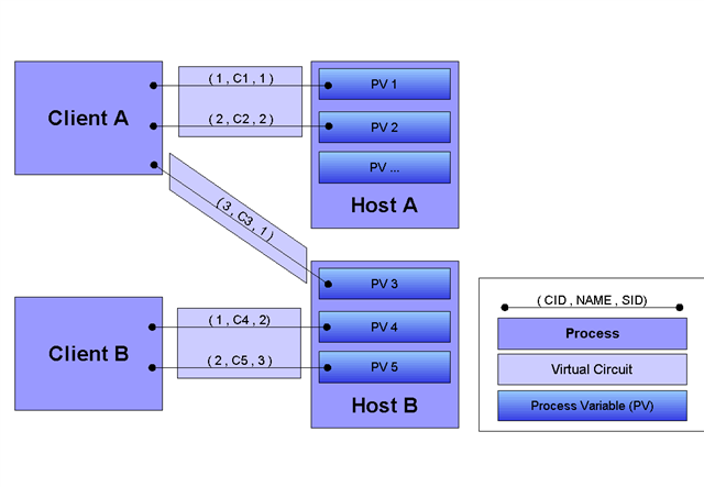
Communication between server and client is performed by sending command messages over UDP and TCP. Client will use UDP to search for hosts and PVs, server will use them to notify its startup and shutdown. Once client requests a specific PV (by specifying its name), UDP message will be broadcast to either a subnet or a list of predefined addresses, and the server which hosts requested PV will respond.
Data exchange between client and server is performed over TCP. After locating the PV, the client will establish a TCP connection to the server. If more that one PV is found to be on the same server, client will use existing TCP connection. Reusable TCP connection between client and server is called Virtual circuit.
Once a virtual circuit is established or already available, channels can be created to PVs.
Let's assume the following setup of PVs and hosts:
- PV "A" is located on host IOC1.
- PV "B" is located on host IOC2.
- PV "C" does not exist on either host.
- PV "D" is located both hosts, IOC1 and IOC2.
A typical scenario would be similar to this:
- User application starts and initializes channel access client library. During initialization, client library might spawn a new repeater process or register with an existing one. If successful, the library is ready to start using the channel access.
- Application will start searching for PVs named "A", "B", "C" and "D". Client will send UDP search packets with "A", "B", "C" and "D" PV names, and wait for an application-specified amount of time. To which network hosts (broadcast or specific IP) these packets are actually sent depends on configuration of the client.
- All hosts that receive this message will check their database and if they know about any of these PV names, they will respond using UDP search response message. Thus, IOC1 will respond with "A" and "D", whereas IOC2 will respond with "B" and "D".
- For each search packet sent, the client will wait for a predefined ammount of time or until response is received.
- In this case (assuming no packet loss in the network), the client will establish a virtual circuit (TCP connection) to IOC1 and IOC2. PV "C" will be assumed to be unavailable at this point and will be ignored. Since "D" is located on both hosts, client will be unable to distinguish between them. First response received will be considered to be proper answer and any additional responses will be considered erroneous and reported to user.
- Once virtual circuits are established, client can access values of "A", "B" and "D". From now on, all messages for either of the PVs will be sent via a corresponding virtual circuit.
- If virtual circuit looses TCP connection or the host disconnects, client will notify application appropriately. Client will also listen for server beacon messages (sent whenever IOC host starts), to be able to restore any lost connections. Beacons are also used to detect when a host stops responding.
- Once the application is done using the channel access library, it will gracefully close any open connections.
2. Data Types
This section defines all primitive data types employed by the CA, as well as their C/C++ equivalents. These data types are referred to in the subsequent sections.
| Type Name | C/C++ | Description |
|---|---|---|
| BYTE | char | Signed 8-bit integer. |
| UBYTE | unsigned char | Unsigned 8-bit integer. |
| INT16 | short | Signed 16-bit integer. |
| UINT16 | unsigned short | Unsigned 16-bit integer. |
| INT32 | int | Signed 32-bit integer. |
| UINT32 | unsigned int | Unsigned 32-bit integer. |
| FLOAT | float | IEEE 32-bit float. |
| DOUBLE | double | IEEE 64-bit float. |
| STRING[n] | char[] | Array of UBYTEs. If [n] is specified, it indicates maximum allowed number of characters in this string including (if neccessary) termination character. |
| TIMESTAMP | None | Timestamp represented with two UINT32 values. First is number of seconds since 0000 Jan 1, 1990. Second is number of nanoseconds within second |
All values are transmitted over the network in big-endian (network) order. For example: UINT32 3145 (0x00000C49) would be sent over the network represented as 00 00 0C 49.
3. Messages
3.1. Message Structure
All channel access messages are composed of a header, followed by the payload.
Header is always present. Its structure is fixed, and contains predefined fields. At the very least, this will be command ID and payload size. Other header fields may carry command-specific meaning. If a field is not used within a certain message, its value must be 0 (0x00).
Payload is a sequence of bytes, which are command and version dependent. Implementation is required to provide proper payload with respect to individual command specification.
Total size of an individual message is limited. With CA versions older than CA_V49, the maximum message size is limited to 16384 (0x4000) bytes. Out of these, header has a fixed size of 16 (0x10) bytes, with the payload having a maximum size of 16368 (0x3ff0) bytes.
Versions CA_V49 and higher may use the extended message form, which allows for larger payloads. The extended message form is indicated by the header fields Payload Size and Data Count being set to 0xffff and 0, respectively. Real payload size and data count are then given as UINT32 type values immediately following the header. Maximum message size is limited by 32-bit unsigned integer representation, 4294967295 (0xffffffff). Maximum payload size is limited to 4294967255 (0xffffffe7).
Extended message form should only be used if payload size actualy exceeds the pre-CA_V49 message size limit of 16368 bytes.
3.1.1. Header
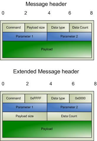
Names of header fields are based on their most common use. Certain messages will use individual fields for purposes other than those described here. These variations are documented for each message individually. All of values in header are unsigned integers.
The common header present in all messages is structured as follows:
| Parameter | Type | Description |
|---|---|---|
| Command | UINT16 | Identifier of the command this message requests. The meaning of other header fields and the payload depends on the command. |
| Payload Size | UINT16 | Size of the payload (in bytes). Must not exceed 0x4000. Value of 0xFFFF indicates extended message. |
| Data Type | UINT16 | Identifier of the data type carried in the payload. Data types are defined in section Payload Data Types (7.). |
| Data Count | UINT16 | Number of elements in the payload. |
| Parameter 1 | UINT32 | Command dependent parameter. |
| Parameter 2 | UINT32 | Command dependent parameter. |
The extended message header (CA_V49 and newer) has the following structure:
| Parameter | Type | Description |
|---|---|---|
| Command | UINT16 | Identifier of the command this message requests. The meaning of other header fields and the payload depends on the command. |
| 0xFFFF | UINT16 | Extended message marker. |
| Data Type | UINT16 | Identifier of the data type carried in the payload. Data types are defined in section Payload Data Types (7.). |
| 0x0000 | UINT16 | Extended message marker. |
| Parameter 1 | UINT32 | Command dependent parameter. |
| Parameter 2 | UINT32 | Command dependent parameter. |
| Payload Size | UINT32 | Size of the payload (in bytes). |
| Data Count | UINT32 | Number of elements in the payload. |
3.1.2. Payload
The structure of the payload depends on the type of the message. The size of the payload matches the Payload Size header field.
 | If the payload size is not a multiple of 8, zero-padding must be performed to achieve 8-byte alignment. |
3.2. Message Identifiers
Some fields in messages serve as identifiers, which must be properly handled by the implementation. These fields serve as identification tokens in asynchronous communication and must be unique within the context of the client library. Recommended scheme for allocating these values is to create them sequentially starting at 0. All IDs are represented with UINT32.
Overflow must be anticipated! Although it is unlikely that an application will need more than 232 different channel IDs, such an overflow can occur with the IOID identifier (see below).
3.2.1. CID - Client ID
CID identifies individual channel within client library context. When a message requires the CID, this value must be passed. CID for a given channel may not change within the lifetime of the channel.
Recommended way of allocating CIDs is sequential 0-based indexing. First client library channel reference that is created has value of 0, second 1, etc. Duplicate CIDs within a single active instance of client library are not allowed.
CID value is passed to the server when the channel is actually connected.
Overflow should be potentially handled, since an application with expected long lifetime and frequent channel allocation and destruction might increase the index frequently. The best way to handle it is to ignore the problem until the first overflow. When that occurs, old CIDs should be no longer relevant, and CID value can be restarted from 0, but excluding any already used values.
3.2.2. SID - Server ID
Performs the same function as CID, but is provided by the server when the channel is connected. SID of channel will never change, unless the channel represented by particular SID is removed from the server during runtime. In that case, the channel will be no longer available.
To handle overflows, the same method could be used as for the Client Channel ID.
3.2.3. Subscription ID
When a subscription is created on a channel (monitor), a unique subscription ID must be provided. Client library will use this ID to identify different subscriptions on the same channel. This value will allow the client library to dispatch monitors appropriately.
Any subscription ID is only valid during the subscription's lifespan. After that, IDs may be reused.
3.2.4. IOID
Unique ID is given to all read and write messages sent by the client library.
ID passed with the request will be returned in the matching response.
Properly handling the wrapping of identifiers is vital to IOID, since an individual ID is used each time a request is made.
4. Commands (TCP and UDP)
The following commands are sent as either UDP datagrams or TCP messages. Some of the messages are also used within the context of a Virtual Circuit.
4.0. CA_PROTO_VERSION
Command: CA_PROTO_VERSION
ID: 0 (0x00)
Description: Exchanges client and server protocol versions and desired circuit priority. This is the first message sent when a new TCP (Virtual Circuit) connection is established. Must be sent before any other exchange between client, server and repeater. The communication is not strictly request response, but will be perceived as such by the implementation. When a new TCP connection is established by the client, CA_PROTO_VERSION is sent. Likewise, the server will accept the connection and send the response form back. Sent over UDP or TCP.
4.0.1. Request
Header
| Field | Value | Description |
|---|---|---|
| Command | 0 | Command identifier for CA_PROTO_VERSION. |
| Payload size | 0 | Must be 0. |
| Priority | Desired priority | Virtual circuit priority. |
| Version | Version number | Minor protocol version number. Only used when sent over TCP. |
| Reserved | 0 | Must be 0. |
| Reserved | 0 | Must be 0. |
Compatibility
| Version | Comment |
|---|---|
| >= CA_V411 | Server will send response immediately after establishing a virtual circuit. |
| < CA_V411 | Message does not include minor version number (it is always 0) and is interpreted as an echo command that carries no data. Version exchange is performed immediately after CA_PROTO_CREATE_CHAN (6.18.). |
Comments
- Priority indicates the server's dispatch scheduling priority which might be implemented by a circuit dedicated thread's scheduling priority in a preemptive scheduled OS.
4.0.2. Response
Header
| Field | Value | Description |
|---|---|---|
| Command | 0 | Command identifier for CA_PROTO_VERSION. |
| Reserved | 0 | Must be 0. |
| Priority | 0 | Must be 0. |
| Version | Version number | Minor protocol version number. Only used when sent over TCP. |
| Reserved | 0 | Must be 0. |
| Reserved | 0 | Must be 0. |
Compatibility
| Version | Comment |
|---|---|
| >= CA_V411 | Server will not respond to request, but send response immediately after establishing a virtual circuit. |
| < CA_V411 | Message does not include minor version number (it is always 0). |
4.6. CA_PROTO_SEARCH
Command: CA_PROTO_SEARCH
ID: 6 (0x06)
Description: Searches for a given channel name. Sent over UDP or TCP.
4.6.1. Request
Header
| Field | Value | Description |
|---|---|---|
| Command | 6 | Command identifier for CA_PROTO_SEARCH. |
| Payload Size | >= 0 | Padded size of channel name. |
| Reply | Reply Flag | Search Reply Flag (8.4.), indicating whether failed search response should be returned. |
| Version | Version Number | Client minor protocol version number. |
| CID | Channel CID | Client allocated CID. |
| CID | Channel CID | Client allocated CID. |
Payload
| Name | Type | Value | Description |
|---|---|---|---|
| Channel name | STRING | Name of channel to search for. |
Comments
- Sent as a UDP datagram.
- It is illegal to specify DO_REPLY flag whenever the message is sending as UDP datagram, regardless of whether broadcast or multicast is used.
- CID will be allocated by the client before this message is sent.
- CID field value is duplicated.
- Reply flag will be generally DONT_REPLY when searching using broadcast and DO_REPLY when searching using unicast. When DO_REPLY is set, server will send a CA_PROTO_NOT_FOUND (4.14.) message indicating it does not have the requested channel.
4.6.2. Response
Header
| Field | Value | Description |
|---|---|---|
| Command | 6 | Command identifier for CA_PROTO_SEARCH. |
| Payload Size | 8 | Payload size is constant. |
| Data Type | Port number | TCP Port number of server that responded. |
| Data Count | 0 | Must be 0. |
| SID | 0xffffffff | Temporary SID, SID - Server ID (3.2.2.). |
| CID | Same as request | Channel CID, CID - Client ID (3.2.1.). |
Payload
| Name | Type | Value | Description |
|---|---|---|---|
| Server protocol version | UINT16 | Server protocol version. |
Comments
- Received as UDP datagram.
- Client channel ID field value (CID) is copied from the request.
- Port number of the server indicates on which port the server that replied listens to. This is used in case more than one server share the same IP.
- Server-assigned channel ID will have value of 0xffffffff, since the SID is not known at this time. Real value will be returned when channel is actually created using CA_CREATE_CHAN.
- In CA_V411 the server's IP address is optionally returned in the CID field of the header allowing a CA server to act as a directory service. If not, then the CID field is set to 0xffffffff.
- The port number included in the header is the *TCP* port of the server. Two servers on the same host can share a UDP port number, but not a TCP port number. Therefore, the port the client needs to connect to in that situation may not be the same as expected if this field in the response is not used.
4.14. CA_PROTO_NOT_FOUND
Command: CA_PROTO_NOT_FOUND
ID: 14 (0x0E)
Description: Indicates that a channel with requested name does not exist. Sent in response to CA_PROTO_SEARCH (4.6.), but only when its DO_REPLY flag was set. Sent over UDP.
4.14.1. Response
Header
| Field | Value | Description |
|---|---|---|
| Command | 14 | Command identifier for CA_PROTO_NOT_FOUND. |
| Reserved | 0 | Must be 0. |
| Reply Flag | DO_REPLY | Same reply flag as in request: always DO_REPLY. |
| Version | Same as request | Client minor protocol version number. |
| CID | Same as request | CID of the channel. |
| CID | Same as request | CID of the channel. |
Comments
- Contents of the header are copied from the request.
- CID fields are diplicated.
- Original request payload is not returned with the response.
4.23. CA_PROTO_ECHO
Command: CA_PROTO_ECHO
ID: 23 (0x17)
Description: Connection verify used by CA_V43. Sent over TCP.
4.23.1. Request
Header
| Field | Value | Description |
|---|---|---|
| Command | 23 | Command identifier for CA_PROTO_ECHO. |
| Reserved | 0 | Must be 0. |
| Reserved | 0 | Must be 0. |
| Reserved | 0 | Must be 0. |
| Reserved | 0 | Must be 0. |
| Reserved | 0 | Must be 0. |
4.23.2. Response
Header
| Field | Value | Description |
|---|---|---|
| Command | 23 | Command identifier for CA_PROTO_ECHO. |
| Reserved | 0 | Must be 0. |
| Reserved | 0 | Must be 0. |
| Reserved | 0 | Must be 0. |
| Reserved | 0 | Must be 0. |
| Reserved | 0 | Must be 0. |
5. Commands (UDP)
The following commands are sent as UDP datagrams.
5.13. CA_PROTO_RSRV_IS_UP
Command: CA_PROTO_RSRV_IS_UP
ID: 13 (0x0D)
Description: Beacon sent by a server when it becomes available. Beacons are also sent out periodically to announce the server is still alive. Another function of beacons is to allow detection of changes in network topology. Sent over UDP.
5.13.1. Response
Header
| Field | Value | Description |
|---|---|---|
| Command | 13 | Command identifier for CA_PROTO_RSRV_IS_UP. |
| Reserved | 0 | Must be 0. |
| Server port | >= 0 | TCP Port the server is listening on. |
| Reserved | 0 | Must be 0. |
| BeaconID | Sequential integers | Sequential Beacon ID. |
| Address | 0 or IP | May contain IP address of the server. |
Comments
- IP field may contain IP of the server. If IP is not present (field Address value is 0), then IP may be substituted by the receiver of the packet (usually repeater) if it is capable of identifying where this packet came from. Any non-zero address must be interpreted as server's IP address.
- BeaconIDs are useful in detecting network topology changes. In certain cases, same packet may be routed using two different routes, causing problems with datagrams. If multiple beacons are received from the same server with same BeaconID, multiple routes are the cause.
- If a server is restarted, it will most likely start sending BeaconID values from beggining (0). Such situation must be anticipated.
5.17. CA_REPEATER_CONFIRM
Command: CA_REPEATER_CONFIRM
ID: 17 (0x11)
Description: Confirms successful client registration with repeater. Sent over UDP.
5.17.1. Response
Header
| Field | Value | Description |
|---|---|---|
| Command | 17 | Command identifier for CA_REPEATER_CONFIRM. |
| Reserved | 0 | Must be 0. |
| Reserved | 0 | Must be 0. |
| Reserved | 0 | Must be 0. |
| Reserved | 0 | Must be 0. |
| Repeater address | IP address | Address with which the registration succeeded. |
Comments
- Since repeater can bind to different local address, its IP is reported in Repeater address.. This address will be either 0.0.0.0 or 127.0.0.1.
5.24. CA_REPEATER_REGISTER
Command: CA_REPEATER_REGISTER
ID: 24 (0x18)
Description: Requests registration with the repeater. Repeater will confirm successful registration using CA_REPEATER_CONFIRM. Sent over TCP.
5.24.1. Request
Header
| Field | Value | Description |
|---|---|---|
| Command | CA_REPEATER_REGISTER | Command identifier |
| Reserved | 0 | Must be 0 |
| Reserved | 0 | Must be 0 |
| Reserved | 0 | Must be 0 |
| Reserved | 0 | Must be 0 |
| Client IP address | IP address | IP address on which the client is listening |
6. Commands (TCP)
The following commands are used within the context of Virtual Circuit and are sent using TCP.
6.1. CA_PROTO_EVENT_ADD
Command: CA_PROTO_EVENT_ADD
ID: 1 (0x01)
Description: Creates a subscription on a channel, allowing the client to be notified of changes in value. A request will produce at least one response. Sent over TCP.
6.1.1. Request
Header
| Field | Value | Description |
|---|---|---|
| Command | 1 | Command identifier for CA_PROTO_EVENT_ADD |
| Payload Size | 16 | Payload size is constant |
| Data Type | Desired DBR type of the return value. | |
| Data Count | >= 0 | Desired number of elements |
| SID | SID of the channel. | SID of the channel on which to reqister this subscription. See SID - Server ID (3.2.2.). |
| SubscriptionID | Client provided Subscription ID | Subscription ID identifying this subscription. See Subscription ID (3.2.3.). |
Payload
| Name | Type | Value | Description |
|---|---|---|---|
| Low val | FLOAT32 | 0.0 | Low value |
| High val | FLOAT32 | 0.0 | High value |
| To val | FLOAT32 | 0.0 | To value |
| Mask | UINT16 | Monitor mask | Mask (8.3.) indicating which events to report |
Comments
- All payload fields except Mask are initialized to 0 and are present only for backward compatibility.
- Successful subscription will result in an immediate response with the current value. Additional responses will be sent as the change occurs based on the Mask parameter.
- Mask defines a filter on which events will be sent.
- A subscription should be destroyed when no longer needed to reduce load on server. See CA_PROTO_EVENT_CANCEL (6.2.).
6.1.2. Response
Header
| Field | Value | Description |
|---|---|---|
| Command | 1 | Command identifier for CA_PROTO_EVENT_ADD |
| Payload Size | >= 0 | Size of the response. |
| Data Type | same as request | Payload data type. |
| Data Count | same as request | Payload data count. |
| Status code | One of ECA codes | Status code (13.) (ECA_NORMAL on success). |
| SubscriptionID | same as request | Subscription ID |
Payload
| Name | Type | Value | Description |
|---|---|---|---|
| Values | DBR | Value stored as DBR type specified in Data Type field. See Payload Data Types (7.). |
Comments
- Response data type and count match that of the request.
- To confirm successful subscription, first response will be sent immediately. Additional responses will be sent as the change occurs based on mask parameters.
6.2. CA_PROTO_EVENT_CANCEL
Command: CA_PROTO_EVENT_CANCEL
ID: 2 (0x02)
Description: Clears event subscription. This message will stop event updates for specified channel. Sent over TCP.
6.2.1. Request
Header
| Field | Value | Description |
|---|---|---|
| Command | 2 | Command identifier for CA_PROTO_EVENT_CANCEL. |
| Payload Size | 0 | Must be 0. |
| Data Type | Same value as in corresponding CA_PROTO_EVENT_ADD (6.1.). | |
| Data Count | >= 0 | Same value as in corresponding CA_PROTO_EVENT_ADD (6.1.). |
| SID | SID of channel | Same value as in corresponding CA_PROTO_EVENT_ADD (6.1.). |
| SubscriptionID | Subscription ID | Same value as in corresponding CA_PROTO_EVENT_ADD (6.1.). |
Comments
- Both SID and SubscriptionID are used to identify which subscription on which monitor to destroy.
- Actual data type and count values are not important, but should be the same as used with corresponding CA_PROTO_EVENT_ADD (6.1.).
6.2.2. Response
Header
| Field | Value | Description |
|---|---|---|
| Command | 1 | Command identifier for CA_PROTO_EVENT_ADD. |
| Payload Size | 0 | Must be 0. |
| Data Type | Same as request. | Same value as CA_PROTO_EVENT_ADD request. |
| Data Count | 0 | Must be 0. |
| SID | Same as request. | Same value as CA_PROTO_EVENT_ADD request. |
| SubscriptionID | Same as request. | Same value as CA_PROTO_EVENT_ADD request. |
Comments
- Notice that the response has CA_PROTO_EVENT_ADD (6.1.) command identifier!
- Regardless of data type and count, this response has no payload.
6.3. CA_PROTO_READ
Command: CA_PROTO_READ
ID: 3 (0x03)
Description:
Read value of a channel. Sent over TCP.
Deprecated since protocol version 3.13.
6.3.1. Request
Header
| Field | Value | Description |
|---|---|---|
| Command | 3 | Command identifier for CA_PROTO_READ_NOTIFY. |
| Payload Size | 0 | Must be 0. |
| Data Type | DBR type | Desired type of the return value. |
| Data Count | >= 0 | Desired number of elements to read. |
| SID | Channel SID | SID of the channel to read. |
| IOID | Client provided IOID | IOID of this operation. |
Comments
- Channel from which to read is identified using SID.
- Response will contain the same IOID as the request, making it possible to distinguish multiple responses.
6.3.2. Response
Header
| Field | Value | Description |
|---|---|---|
| Command | 3 | Command identifier for CA_PROTO_READ_NOTIFY. |
| Payload size | Size of payload | Size of DBR formatted data in payload. |
| Data type | DBR type | Payload format. |
| Data count | >= 0 | Payload element count. |
| SID | Same as request | SID of the channel. |
| IOID | Same as request | IOID of this operation. |
Payload
| Name | Type | Value | Description |
|---|---|---|---|
| DBR formatted data | DBR | DBR formatted data | Value stored as DBR type specified in Data type field. Data count specifies number of elements of DBR value field. |
6.4. CA_PROTO_WRITE
Command: CA_PROTO_WRITE
ID: 4 (0x04)
Description: Writes new channel value. Sent over TCP.
6.4.1. Request
Header
| Field | Value | Description |
|---|---|---|
| Command | CA_PROTO_WRITE | Command identifier |
| Payload size | Size of DBR formatted payload | Size of padded payload |
| Data type | DBR type | Format of payload |
| Data count | ELEMENT_COUNT | Number of elements in payload |
| SID | SID provided by server | Server channel ID |
| IOID | Client provided IOID | Request ID |
Payload
| Name | Type | Value | Description |
|---|---|---|---|
| DBR formatted data | DBR | DBR formatted data | Value stored as DBR type specified in Data type field. Data count specifies number of elements of DBR value field. |
Comments
- There is no response to this command.
6.5. CA_PROTO_SNAPSHOT
Command: CA_PROTO_SNAPSHOT
ID: 5 (0x05)
Description: Obsolete.
6.7. CA_PROTO_BUILD
Command: CA_PROTO_BUILD
ID: 7 (0x07)
Description: Obsolete.
6.8. CA_PROTO_EVENTS_OFF
Command: CA_PROTO_EVENTS_OFF
ID: 8 (0x08)
Description: Disables a server from sending any subscription updates over this virtual circuit. Sent over TCP. This mechanism is used by clients with slow CPU to prevent congestion when they are unable to handle all updates recived. Effective automated handling of flow control is beyond the scope of this document.
6.8.1. Request
Header
| Field | Value | Description |
|---|---|---|
| Command | 8 | Command identifier for CA_PROTO_EVENTS_OFF |
| Reserved | 0 | Must be 0. |
| Reserved | 0 | Must be 0. |
| Reserved | 0 | Must be 0. |
| Reserved | 0 | Must be 0. |
| Reserved | 0 | Must be 0. |
Comments
- This request will disable sending of subscription updates on the server to which it is sent.
- Command applies to a single virtual circuit, so having multiple priority virtual circuit connections to the server would only affect the one on which the message is sent.
- No response will be sent for this request.
6.9. CA_PROTO_EVENTS_ON
Command: CA_PROTO_EVENTS_ON
ID: 9 (0x09)
Description: Enables the server to resume sending subscription updates for this virtual circuit. Sent over TCP. This mechanism is used by clients with slow CPU to prevent congestion when they are unable to handle all updates recived. Effective automated handling of flow control is beyond the scope of this document.
6.9.1. Request
Header
| Field | Value | Description |
|---|---|---|
| Command | 9 | Command identifier for CA_PROTO_EVENTS_ON |
| Reserved | 0 | Must be 0. |
| Reserved | 0 | Must be 0. |
| Reserved | 0 | Must be 0. |
| Reserved | 0 | Must be 0. |
| Reserved | 0 | Must be 0. |
Comments
- This request will enable sending of subscription updates on the server to which it is sent.
- Command applies to a single virtual circuit, so having multiple priority virtual circuit connections to the server would only affect the one on which the message is sent.
- No response will be sent for this request.
6.10. CA_PROTO_READ_SYNC
Command: CA_PROTO_READ_SYNC
ID: 10 (0x0A)
Description: Deprecated since protocol version 3.13.
6.10.1. Request
Header
| Field | Value | Description |
|---|---|---|
| Command | 10 | Command identifier for CA_PROTO_READ_SYNC. |
| Reserved | 0 | Must be 0. |
| Reserved | 0 | Must be 0. |
| Reserved | 0 | Must be 0. |
| Reserved | 0 | Must be 0. |
| Reserved | 0 | Must be 0. |
6.11. CA_PROTO_ERROR
Command: CA_PROTO_ERROR
ID: 11 (0x0B)
Description: Sends error message and code. This message is only sent from server to client in response to any request that fails and does not include error code in response. This applies to all asynchronous commands. Error message will contain a copy of original request and textual description of the error. Sent over UDP.
6.11.1. Response
Header
| Field | Value | Description |
|---|---|---|
| Command | 11 | Command identifier for CA_PROTO_ERROR |
| Payload Size | Size of the request header that triggered the error plus size of the error message. | |
| Reserved | 0 | Must be 0. |
| Reserved | 0 | Must be 0. |
| CID | Channel CID | CID of the channel for which request failed, CID - Client ID (3.2.1.). |
| Status Code | One of ECA codes | Error status code (13.). |
Payload
| Name | Type | Value | Description |
|---|---|---|---|
| Original Request | Message Header | Header of the request that caused the error. | |
| Error Message | STRING | A null-terminated string conveying the error message. |
Comments
- Complete exception report is returned. This includes error message code, CID of channel on which the request failed, original request and string description of the message.
- CID value depends on original request and may not actually identify a channel.
- First part of payload is original request header with the same structure as sent. Any payload that was part of this request is not included. Textual error message starts immediately after the header.
6.12. CA_PROTO_CLEAR_CHANNEL
Command: CA_PROTO_CLEAR_CHANNEL
ID: 12 (0x0C)
Description: Clears a channel. This command will cause server to release the associated channel resources and no longer accept any requests for this SID/CID.
6.12.1. Request
Header
| Field | Value | Description |
|---|---|---|
| Command | 12 | Command identifier of CA_PROTO_CLEAR_COMMAND |
| Reserved | 0 | Must be 0. |
| Reserved | 0 | Must be 0. |
| Reserved | 0 | Must be 0. |
| SID | SID of the channel | SID of channel to clear. |
| CID | CID of the channel | CID of channel to clear. |
6.12.2. Response
Header
| Field | Value | Description |
|---|---|---|
| Command | 12 | Command identifier of CA_PROTO_CLEAR_COMMAND |
| Reserved | 0 | Must be 0. |
| Reserved | 0 | Must be 0. |
| Reserved | 0 | Must be 0. |
| SID | Same as request | SID of cleared channel. |
| CID | Same as request | CID of cleared channel. |
Comments
- Server responds immediately and only then releases channel resources.
- Once a channel with a given SID has been cleared, any request sent with this SID will fail.
- Sent over TCP.
6.15. CA_PROTO_READ_NOTIFY
Command: CA_PROTO_READ_NOTIFY
ID: 15 (0x0F)
Description: Read value of a channel. Sent over TCP.
6.15.1. Request
Header
| Field | Value | Description |
|---|---|---|
| Command | 15 | Command identifier for CA_PROTO_READ_NOTIFY. |
| Payload Size | 0 | Must be 0. |
| Data Type | DBR type | Desired type of the return value. |
| Data Count | >= 0 | Desired number of elements to read. |
| SID | Channel SID | SID of the channel to read. |
| IOID | Client provided IOID | IOID of this operation. |
Comments
- Channel from which to read is identified using SID.
- Response will contain the same IOID as the request, making it possible to distinguish multiple responses.
6.15.2. Response
Header
| Field | Value | Description |
|---|---|---|
| Command | 15 | Command identifier for CA_PROTO_READ_NOTIFY. |
| Payload size | Size of payload | Size of DBR formatted data in payload. |
| Data type | DBR type | Payload format. |
| Data count | >= 0 | Payload element count. |
| SID | Same as request | SID of the channel. |
| IOID | Same as request | IOID of this operation. |
Payload
| Name | Type | Value | Description |
|---|---|---|---|
| DBR formatted data | DBR | DBR formatted data | Value stored as DBR type specified in Data type field. Data count specifies number of elements of DBR value field. |
6.16. CA_PROTO_READ_BUILD
Command: CA_PROTO_READ_BUILD
ID: 16 (0x10)
Description: Obsolete
6.16.1. Request
6.18. CA_PROTO_CREATE_CHAN
Command: CA_PROTO_CREATE_CHAN
ID: 18 (0x12)
Description: Requests creation of channel. Server will allocate required resources and return initialized SID. Sent over TCP.
6.18.1. Request
Header
| Field | Value | Description |
|---|---|---|
| Command | 18 | Command identifier for CA_PROTO_CREATE_CHAN |
| Payload size | Size of payload | Padded length of channel name. |
| Reserved | 0 | Must be 0. |
| Reserved | 0 | Must be 0. |
| CID | Channel CID | CID of the channel to create. |
| Client version | Version number | Client minor protocol version. |
Payload
| Name | Type | Value | Description |
|---|---|---|---|
| Channel name | STRING | Name of channel to create. |
Comments
- CID sent should be the same as used with CA_PROTO_SEARCH.
6.18.2. Response
Header
| Field | Value | Description |
|---|---|---|
| Command | CA_PROTO_CREATE_CHAN | |
| Payload size | 0 | Must be 0 |
| Data type | DBR type | Native channel data type |
| Data count | >= 0 | Native channel data count |
| CID | Same as request | Channel client ID |
| SID | SID provided by server | Channel server ID |
Comments
- SID will be associated with CID on the server and will be reused sending certain commands that require it as a parameter.
- SID will be valid until the channel is cleared using CA_PROTO_CLEAR or server destroys the PV the channel references.
6.19. CA_PROTO_WRITE_NOTIFY
Command: CA_PROTO_WRITE_NOTIFY
ID: 19 (0x13)
Description: Writes new channel value. Sent over TCP.
6.19.1. Request
Header
| Field | Value | Description |
|---|---|---|
| Command | CA_PROTO_WRITE_NOTIFY | Command identifier |
| Payload size | Size of DBR formatted payload | Size of padded payload |
| Data type | DBR type | Format of payload |
| Data count | ELEMENT_COUNT | Number of elements in payload |
| SID | SID provided by server | Server channel ID |
| IOID | Client provided IOID | Request ID |
Payload
| Name | Type | Value | Description |
|---|---|---|---|
| DBR formatted data | DBR | DBR formatted data | Value stored as DBR type specified in Data type field. Data count specifies number of elements of DBR value field. |
6.19.2. Response
Header
| Field | Value | Description |
|---|---|---|
| Command | CA_PROTO_WRITE_NOTIFY | Command identifier |
| Payload size | 0 | Must be 0 |
| Data type | Same as request | Format of data written |
| Data count | Same as request | Number of elements written |
| Status | Status code | Status of write success |
| IOID | Same as request | Request ID |
6.20. CA_PROTO_CLIENT_NAME
Command: CA_PROTO_CLIENT_NAME
ID: 20 (0x14)
Description: Sends local username to virtual circuit peer. This name identifies the user and affects access rights.
6.20.1. Request
Header
| Field | Value | Description |
|---|---|---|
| Command | CA_PROTO_CLIENT_NAME | Command identifier |
| Payload size | >=0 | Length of string in payload |
| Reserved | 0 | Must be 0 |
| Reserved | 0 | Must be 0 |
| Reserved | 0 | Must be 0 |
| Reserved | 0 | Must be 0 |
Payload
| Name | Type | Value | Description |
|---|---|---|---|
| User name | STRING | 0-terminated username string |
Comments
- This is a one-way message and will not receive response.
- String in payload must be 0 padded to a length that is multiple of 8.
- Sent over TCP.
6.21. CA_PROTO_HOST_NAME
Command: CA_PROTO_HOST_NAME
ID: 21 (0x15)
Description: Sends local host name to virtual circuit peer. This name will affect access rights. Sent over TCP.
6.21.1. Request
Header
| Field | Value | Description |
|---|---|---|
| Command | 21 | Command identifier for CA_PROTO_HOST_NAME. |
| Payload size | Size of payload | Length of host name string. |
| Reserved | 0 | Must be 0. |
| Reserved | 0 | Must be 0. |
| Reserved | 0 | Must be 0. |
| Reserved | 0 | Must be 0. |
Payload
| Name | Type | Value | Description |
|---|---|---|---|
| Host name | STRING | Client host name. |
Comments
- This is one-way message and will receive no response.
6.22. CA_PROTO_ACCESS_RIGHTS
Command: CA_PROTO_ACCESS_RIGHTS
ID: 22 (0x16)
Description: Notifies of access rights for a channel. This value is determined based on host and client name and may change during runtime. Client cannot change access rights nor can it explicitly query its value, so last received value must be stored.
6.22.1. Response
Header
| Field | Value | Description |
|---|---|---|
| Command | 22 | Command identifier for CA_PROTO_ACCESS_RIGHTS. |
| Payload size | 0 | Must be 0. |
| Reserved | 0 | Must be 0. |
| Reserved | 0 | Must be 0. |
| CID | Channel CID | Channel affected by change. |
| Access Rights | Access Rights | Access rights (8.5.) for given channel. |
Comments
- Access Rights affect CA_PROTO_READ_NOTIFY, CA_PROTO_WRITE_NOTIFY and CA_PROTO_WRITE.
- CA_PROTO_ACCESS_RIGHTS will be sent immediately after a channel is created using CA_PROTO_CREATE_CHAN. If they change during runtime, this message sent to report new value.
- Changes are only sent to currently connected channels, since it requires valid CID.
- Sent over TCP.
6.25. CA_PROTO_SIGNAL
Command: CA_PROTO_SIGNAL
ID: 25 (0x19)
Description: Obsolete.
6.26. CA_PROTO_CREATE_CH_FAIL
Command: CA_PROTO_CREATE_CH_FAIL
ID: 26 (0x1A)
Description: Reports that channel creation failed. This response is sent to when channel creation in CA_PROTO_CREATE_CHAN fails.
6.26.1. Response
Header
| Field | Value | Description |
|---|---|---|
| Command | CA_PROTO_CREATE_CH_FAIL | Command identifier |
| Reserved | 0 | Must be 0 |
| Reserved | 0 | Must be 0 |
| Reserved | 0 | Must be 0 |
| CID | Same as request | Client channel ID |
| Reserved | 0 | Must be 0 |
Comments
- Sent over TCP.
6.27. CA_PROTO_SERVER_DISCONN
Command: CA_PROTO_SERVER_DISCONN
ID: 27 (0x1B)
Description: Notifies the client that server has disconnected the channel. This may be since the channel has been destroyed on server. Sent over TCP.
6.27.1. Response
Header
| Field | Value | Description |
|---|---|---|
| Command | CA_PROTO_SERVER_DISCONN | Command identifier |
| Reserved | 0 | Must be 0 |
| Reserved | 0 | Must be 0 |
| Reserved | 0 | Must be 0 |
| CID | CID provided by client | CID that was provided during CA_PROTO_CREATE_CHAN |
| Reserved | 0 | Must be 0 |
7. Payload Data Types
Channel access defines special structures to transferring data. Main reason is efficiency, since in many cases more than one value can be transferred. These types are organized in typed hierarchies with loose inheritance. There are seven basic data types: DBR_STRING, DBR_SHORT, DBR_INT, DBR_FLOAT, DBR_ENUM, DBR_CHAR, DBR_LONG and DBR_DOUBLE. Each of these types can be represented as an array, if the corresponding field in header indicates that.
Additional to basic data types, structured types allow access to more than one value within the same record. These structures are status (STS), time stamp (TIME), graphic (GR) and control (CTRL). All these structures contain value as the last field.
Status structure adds alarm severity. Time stamp structures extends the status structure by adding time stamp of the value. Graphic extends status structure by providing alarm limits, units and precision. Control structure extends graphic by adding control limits.
Following is the list of all structures as transmitted over network.
7.7. DBR_STS_STRING
Type: DBR_STS_STRING
ID: 7 (0x07)
Description: DBR_STS structure for string type.
7.8. DBR_STS_SHORT
Type: DBR_STS_SHORT
ID: 8 (0x08)
Description: DBR_STS structure for UINT16 type. May be referred to as DBR_STS_INT.
7.9. DBR_STS_FLOAT
Type: DBR_STS_FLOAT
ID: 9 (0x09)
Description: DBR_STS structure for FLOAT type.
7.10. DBR_STS_ENUM
Type: DBR_STS_ENUM
ID: 10 (0x0A)
Description: DBR_STS structure for ENUM type.
7.11. DBR_STS_CHAR
Type: DBR_STS_CHAR
ID: 11 (0x0B)
Description: DBR_STS structure for CHAR type.
7.12. DBR_STS_LONG
Type: DBR_STS_LONG
ID: 12 (0x0C)
Description: DBR_STS structure for LONG type.
7.13. DBR_STS_DOUBLE
Type: DBR_STS_DOUBLE
ID: 13 (0x0D)
Description: DBR_STS structure for LONG type.
7.14. DBR_TIME_STRING
Type: DBR_TIME_STRING
ID: 14 (0x0E)
Description: DBR_TIME structure for string type.
7.15. DBR_TIME_SHORT
Type: DBR_TIME_SHORT
ID: 15 (0x0F)
Description: DBR_TIME structure for UINT16 type. May be referred to as DBR_TIME_INT.
7.16. DBR_TIME_FLOAT
Type: DBR_TIME_FLOAT
ID: 16 (0x10)
Description: DBR_TIME structure for FLOAT type.
7.17. DBR_TIME_ENUM
Type: DBR_TIME_ENUM
ID: 17 (0x11)
Description: DBR_TIME structure for ENUM type.
7.18. DBR_TIME_CHAR
Type: DBR_TIME_CHAR
ID: 18 (0x12)
Description: DBR_TIME structure for CHAR type.
7.19. DBR_TIME_LONG
Type: DBR_TIME_LONG
ID: 19 (0x13)
Description: DBR_TIME structure for LONG type.
7.20. DBR_TIME_DOUBLE
Type: DBR_TIME_DOUBLE
ID: 20 (0x14)
Description: DBR_TIME structure for DOUBLE type.
7.21. DBR_GR_STRING
Type: DBR_GR_STRING
ID: 21 (0x15)
Description: DBR_GR structure for string type.
7.22. DBR_GR_SHORT
Type: DBR_GR_SHORT
ID: 22 (0x16)
Description: DBR_GR structure for short type.
7.22. DBR_GR_INT
Type: DBR_GR_INT
ID: 22 (0x16)
Description: DBR_GR structure for int type.
7.23. DBR_GR_FLOAT
Type: DBR_GR_FLOAT
ID: 23 (0x17)
Description: DBR_GR structure for float type.
7.24. DBR_GR_ENUM
Type: DBR_GR_ENUM
ID: 24 (0x18)
Description: DBR_GR structure for ENUM type.
7.25. DBR_GR_CHAR
Type: DBR_GR_CHAR
ID: 25 (0x19)
Description: DBR_GR structure for char type (UINT8 representation).
7.26. DBR_GR_LONG
Type: DBR_GR_LONG
ID: 26 (0x1A)
Description: DBR_GR structure for long type (INT32 representation).
7.27. DBR_GR_DOUBLE
Type: DBR_GR_DOUBLE
ID: 27 (0x1B)
Description: DBR_GR structure for double type.
7.28. DBR_CTRL_STRING
Type: DBR_CTRL_STRING
ID: 28 (0x1C)
Description: DBR_CTRL structure for string type.
7.29. DBR_CTRL_SHORT
Type: DBR_CTRL_SHORT
ID: 29 (0x1D)
Description: DBR_CTRL structure for short type.
7.29. DBR_CTRL_INT
Type: DBR_CTRL_INT
ID: 29 (0x1D)
Description: DBR_CTRL structure for INT16 type.
7.30. DBR_CTRL_FLOAT
Type: DBR_CTRL_FLOAT
ID: 30 (0x1E)
Description: DBR_CTRL structure for float type.
7.31. DBR_CTRL_ENUM
Type: DBR_CTRL_ENUM
ID: 31 (0x1F)
Description: DBR_CTRL structure for ENUM type.
7.32. DBR_CTRL_CHAR
Type: DBR_CTRL_CHAR
ID: 32 (0x20)
Description: DBR_CTRL structure for char type (UINT8 representation).
7.33. DBR_CTRL_LONG
Type: DBR_CTRL_LONG
ID: 33 (0x21)
Description: DBR_CTRL structure for INT32 type.
7.34. DBR_CTRL_DOUBLE
Type: DBR_CTRL_DOUBLE
ID: 34 (0x22)
Description: DBR_CTRL structure for DOUBLE type.
8. Constants
8.1. Port numbers
Although there is no requirement as to which port numbers are used by either servers or clients, there are some standard values which must be used as defaults, unless overriden by application.
Port numbers are dependant on protocol versions and are calculated using the folowing definitions:
CA_PORT_BASE = 5056
CA_SERVER_PORT = CA_PORT_BASE + MAJOR_PROTOCOL_VERSION * 2
CA_REPEATER_PORT = CA_PORT_BASE + MAJOR_PROTOCOL_VERSION * 2 + 1
Based on protocol version described in this document (4.11), port numbers used are CA_SERVER_PORT = 5064 and CA_REPEATER_PORT = 5065.
Since registration of port numbers with IANA and in the interest of compatibility, the version numbers are unlikely to change. Therefore, the port numbers described here (5064 and 5065) may be considered final.
8.2. Representation of constants
This section lists various constants, their types and values used by protocol.
Some constants can be combined using logical OR operation. Example: Monitor mask of DBE_VALUE and DBE_ALARM are combined using (DBE_VALUE or DBE_ALARM) resulting in (1 or 4 == 5).
To query the whether certain value is present in such combined value, and operation is used. Example: to query whether DBE_ALARM of monitor mask is set, (DBE_VALUE and MASK > 0) will return 0 if DBE_VALUE is not present, otherwise DBE_ALARM is present.
8.3. Monitor Mask
Indicates which changes to the value should be reported back to client library. Different values can be combined using logical OR operation.
Type: not defined, depends on the field it is in (usually UINT16)
- DBE_VALUE - value 1 (0x01) - Value change events are reported. Value changes take into consideration a dead band within which the value changes are not reported.
- DBE_LOG - value 2 (0x02) - Log events are reported. Similiar to DBR_VALUE, DBE_LOG defines a different dead band value that determines frequency of updates.
- DBE_ALARM - value 4 (0x04) - Alarm events are reported whenever alarm value of the channel changes.
8.4. Search Reply Flag
Indicates whether server should reply to failed search messages. If a server does not know about channel name, it has the option of replying to request or ignoring it. Usually, servers contacted through address list will receive request for reply.
Type: not defined, depends on the field it is in (usually UINT16).
- DO_REPLY - value 10 (0x0a) - Server should reply to failed search requests.
- DONT_REPLY - value 5 (0x05) - Server should ignore failed requests.
8.5. Access Rights
Defines access rights for a given channel. Accss rights are defined as logicaly ORred value of allowed access.
Type: not defined, depends on the field it is in (usually UINT16).
- CA_PROTO_ACCESS_RIGHT_READ - value 1 (0x01) - Read access is allowed
- CA_PROTO_ACCESS_RIGHT_WRITE - value 2 (0x02) - Write access is allowed.
As a reference, the following values are valid.
- 0 - No access
- 1 - Read access only
- 2 - Write access only
- 3 - Read and write access
9. Example message
This example shows construction of messages. For details of individual structures, see message and data type reference (CA_PROTO_READ_NOTIFY and DBR_GR_INT16).
A client will send CA_PROTO_READ_NOTIFY message with the following contents.
- Data type: DBR_GR_INT16
- Element count: 5
- Server ID: 22 (obtained during channel creation)
- Sequence ID: 56 (each read or write request increases value by one)
The messsage would be represented as follows:
00 0F (command) 00 00 (payload size) 00 16 (data type) 00 05 (element count) 00 00 00 16 (server ID) 00 00 00 38 (sequence ID) |
Server would respond with success and return requested value with individual DBR_GR_INT16 fields having the following values.
- Status: ECA_NORMAL
- Severity: NO_ALARM (0)
00 0f (command) 00 20 (payload size) 00 16 (data type) 00 05 (element count)
00 00 00 16 (server ID) 00 00 00 38 (sequence ID)
00 05  00 02  43 6f 75 6e 74 73 00 00  00 0a  00 00
00 08  00 06  00 04  00 02  00 00  00 00  00 00 00 00
    8      6      4      2      0      0      0     0
|
10. Virtual Circuit Operation
10.1. Establishing virtual circuit
Virtual circuit is a TCP connection between a client and a server. Each virtual circuit has an associated priority, which can be used by server to prioritize requests depending on current load. An independent circuit for each priority level selected by the client might be used because it allows for preemptive prioritized dispatch scheduling in the server when the OS supports that, and also allows specifying the networks scheduling priority when the router and or LAN support that. Regardless of how many channels are handled by either client or server, each client-server pair will be connected with exactly one TCP connection for each priority level. This level is specified when creating a virtual circuit.
When establishing a virtual circuit, a simple handshake will be performed. Client will open a TCP connection to the server. After that, it sends CA_PROTO_VERSION (4.0.), CA_PROTO_CLIENT_NAME (6.20.) and CA_PROTO_HOST_NAME (6.21.) messages. If server accepts all the supplied parameters and the client and host are permitted to connect, the server will respond with CA_PROTO_VERSION (4.0.). After that, client may start sending requests.
Virtual circuit will remain active as long as there is at least one channel active. If the TCP connection is lost, all channels using this circuit must be notified.
10.2. Basic mode of operation
In most basic role, the client will send requests to the server and await one or more responses, or in some special cases, no response will be expected. For each type of request, one of three events will occur:
- Matching response will be received
- Error response will be received by client indicating either user or client error
- The client will receive no response, and one was expected.
- Network failure occurs
When a matching response is received, the operation has completed successfully. Any result returned will report any applicable return information. Client library will then notify the client about completion.
If a request fails and server could handle this failure, CA_PROTO_ERROR (6.11.) response will be received or error code is received in response, depending on the request sent. This response contains original request header, error code and text description of error.
Although servers are designed to always return a response, in some cases this will not occur. An unlikely case is that a server has failed or stopped responding. A more common case is broadcast search, where no replies are sent to search messages. The later case is designed to not overload the network by sending failure notifications. This however does not allow client library to determine, whether a search has failed, or the server load is simply too high and the response will arrive later. In this case, client library may assume that search yielded no results and notify on search failure. Regardless of this, should any such response arrive late, the client must be notified.
In case of network failure, two situations should be anticipated. One is TCP connection loss for a virtual circuit. Virtual circuit has mechanisms for dealing with such case and should attempt to restore the connection itself. Repeater has no such mechanisms, since it depends on reliability of UDP protocol. There will be in most cases no way for repeater to determine, whether the packets sent actually arrive at destination. Repeater can however verify the clients registered with it, by attempting to bind to their port. If binding succeeds, the client no longer exists. Alternate way is using connected UDP sockets and checking ICMP destination unreachable error.
10.3. Detecting virtual circuit unresponsiveness
During virtual circuit life-time, the circuit may become unresponsive. Since this is tightly related to network availability and server load, determining actual cause for unresponsiveness is difficult. Basic criteria on which unresponsiveness should be determined are:
- No beacon received from server in expected time period
- No response received from server for a predetermined ammount of time (usually 30 seconds)
- Server does not immediatelly respond to CA_PROTO_ECHO (4.23.)
Behaviour of virtual circuit implementation under such conditions is undefined. Experience has shown however, that virtual circuit should not be disconnected when it becomes unresponsive, since this negatively impacts network performance under load.
10.4. Channel life-cycle
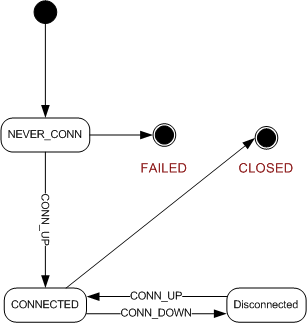
A channel discussed here is based on two levels. One is channel as seen from client application, the other is channel implementation in client library. This difference will be pointed out where applicable.
When a channel is created by client application, it is initialized in NEVER_CONN state. This indicates that channel is currently being connected for the first time. If connection process fails, channel moves into FAILED state and is not usable. Connection proccess within the client library will attempt to connect the channel repeatedly. Intervals between consecutive attempts should be increased, before finally giving up and determining the channel cannot be connected and signaling FAILED state. A total number of attempts can be on the order of 100.
When connection is established, the channel will signal to client with CONN_UP event and changing its state to connected.
Should the virtual circuit connection be lost, CONN_DOWN event will change channel state to disconnected. Whenever virtual circuit is reconnected, the channel state is restored to connected. Note that reconnection process follows the same rules as initial process. It is also possible, that the PV will move between the servers, but client application should not be aware of such internal changes to channel.
Once client application is done using the channel, it will be closed and its state moved changed to CLOSED. After that, this channel can no longer be used.
Detailed description of channel operations is outlined below.
10.5. Connecting a Channel
Connection of a channel is a two phase process. First, server that hosts channel with a given name must be located. Second, client and server must both register a connection.
Before connection, client library allocates CID identifier that will be used to reference new channel. Next it sends CA_PROTO_SEARCH (4.6.) with channel name request via broadcast and/or to address list. Each server that receives such message checks to see if it knows about this name. If it does, response to CA_PROTO_SEARCH (4.6.) is sent back to client. If not, the server checks if reply field of request is DO_REPLY and responds with CA_PROTO_NOT_FOUND (4.14.), otherwise does nothing.
Client library may receive more than one response. In this case, first response should be used and others rejected. The cause of multiple responses is same PV hosted on multiple different hosts. Client or server has no method of knowing which PV is 'right'. Multiple responses should be reported by the client to the application or user.
After extracting server address and port, client library checks to see if this server is already known and connected via virtual circuit. If not, virtual circuit is established. Any requests sent through this channel will use this circuit.
For this it sends CA_PROTO_CREATE_CHAN (6.18.) request with channels CID and channel name. Server will respond with CA_PROTO_CREATE_CHAN (6.18.) response which will provide channel type, data count and server identifier SID. In case the channel could not be created, error message will be returned.
Having initialized both CID and SID and registered the channel with the server, this channel is ready for use. Client library should store these values for further use.
10.6. Read and Write operations
Read and write operations require the channel to be properly initialized and connected and its virtual circuit to be active. These operations use CA_PROTO_READ_NOTIFY (6.15.) and CA_PROTO_WRITE_NOTIFY (6.19.) messages.
To read a value from a channel client library will create a CA_PROTO_READ_NOTIFY (6.15.) request. This request will contain desired data type and data count parameters which may differ from channels native type as obtained during connect. Additionally, IOID is stored in request to provide unique identification. Channel that is used will be identified by SID that was obtained during channel creation. No payload is sent with request.
After server processes the message reponse is either valid CA_PROTO_READ_NOTIFY (6.15.) response or CA_PROTO_ERROR (6.11.) to indicate error. In case of success, response contains same field values as request, but has additional payload. This payload is formatted as requested data type with desired number of elements.
Write operation is performed identically with payload roles reversed. Here the request will contain payload with DBR formatted value to write and response will have no payload.
10.7. Subscriptions and Monitors
Client creates monitors by registering a subscription on a channel. This causes server to notify subscribers of value changes.
Subscriptions are created by first allocating unique Subscription ID. This identifier is used to uniquely identify various subscriptions. Next, CA_PROTO_EVENT_ADD (6.1.) request is created using SID and Subscription ID. Data type and data count indicate desired value format in response. Additional information is provided in payload as specified in CA_PROTO_EVENT_ADD (6.1.) reference.
First CA_PROTO_EVENT_ADD (6.1.) response is received immediatelly to confirm successful subscription. If error occurs, CA_PROTO_ERROR (6.11.) response is received.
Responses arrive asynchronously until client cancels the subscription using CA_PROTO_EVENT_ADD (6.1.) response and payload containing DBR formatted value. If server is shutdown during this time, events will no longer arrive, but the subscription will not be cancelled. Once the server is restarted, client library will reestablish the subscription silently without notifying client application.
Subscription is cancelled by sending CA_PROTO_EVENT_CANCEL (6.2.) request with relevant parameters identical to those in original CA_PROTO_EVENT_ADD (6.1.) request that created the subscription. Successful cancelation is confirmed by CA_PROTO_EVENT_ADD (6.1.) response without payload.
Cancelling the subscription while the server is down should be handled by cancelling the subscription locally and not reestablishing it once the server is up again.
10.8. Connection events
If a virtual circuit is disconnected (server goes down or stops sending beacons), any connected channels that use this circuit should be notified. There is no direct way to reconnect the channel from client side, but this will be done by the library. Once the circuit is reestablished, client application is notified of status change for all channels. Even if a channel is reported to be disconnect as a result of virtual circuit failure, the channel is not closed. The only way a channel connection is actually closed is by explicitly closing it using CA_PROTO_CLEAR_CHANNEL (6.12.) thereby invalidating its resources.
10.9. Closing the channel
Channel is closed by sending CA_PROTO_CLEAR_CHANNEL (6.12.) request. Regardless of whether response confirmes closing or reports an error, CID and SID associated with the channel are no longer valid. Any resources still available to the client application are considered invalid. A channel that was cleared may no longer be reconnected.
11. Repeater Operation
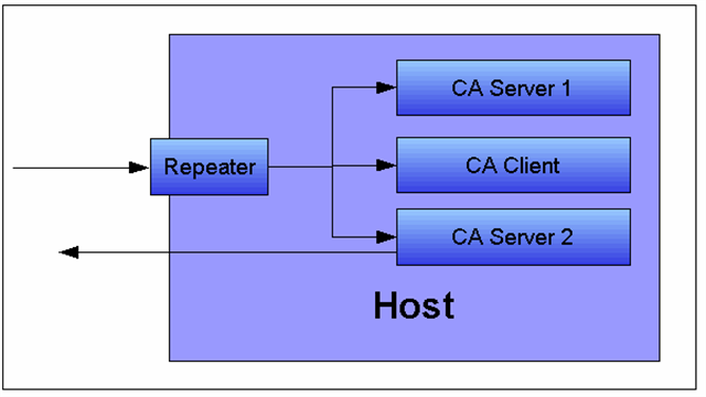
11.1. Role
Simple demonstration of repeater operation. A repeater will be used both on client and server side to forward incoming UDP requests to multiple clients and/or server on same host. Each host or client will then respond on its own.
Since role of the repeater is related to host, not the client, its implementation must be independant from individual client instance or process. Repeater must not stop operation until all clients depending on it registered with it have shut down.
11.2. Startup
Each client must check for presence of repeater on startup, before any access to EPICS hosts is made. This check is made by attempting to bind to CA_REPEATER_PORT. If binding fails, the client may assume the repeater is already running and may attempt to register. This is done by sending CA_REPEATER_REGISTER datagram to CA_REPEATER_PORT. If repeater is already active, it will respond with CA_REPEATER_CONFIRM datagram back to client, otherwise the client can assume, the repeater is invalid, the process bound to the port is not even a repeater or that some unknown error occured. In this case, client will spawn new repeater and attempt registration again. Attempt to detect the repeater and register should be made several times with some reasonable delay to avoid any transient unresponsiveness that might occur.
After the client has received registration confirmation from the repeater, it should keep listening for messages from the repeater. Any broadcasts sent by servers will be received by the repeater and forwarded to registered clients.
11.3. Client detection
The repeater tests to see if its clients exist by periodically attempting to bind to their ports. If unsuccessful when attempting to bind to the client's port, then the repeater concludes that the client no longer exists. A technique using connected UDP sockets and ICMP destination unreachable can also used. If a client is determined to no longer be present then the repeater un-registers that client and no longer sends messages to it.
11.4. Operation
Each message, the repeater receives, must be forwarded to local clients, to the address provided during registration. No assumption should be made about existence or state of clients.
11.5. Shutdown
Repeater should not shutdown on its own, if it does, there should be no active clients registered with it.
12. Server Beacons
Each EPICS server will send beacons periodically to report it is still active. Beacon messages will contain server's IP and port, as well as sequential beacon ID. Beacons will be broadcast and sent to servers address list.
When a server becomes active, it will immediately start sending beacons with an increasing delay. Time between beacons will start at 0.02 seconds. After each beacon is sent, this time is doubled. Maximum delay between beacons will be limited by server specified parameter, but is commonly 15 seconds.
If a beacon is not received within expected time, virtual circuits connected to this server should be notified and virtual circuit must handle this situation.
13. Return Codes
This section covers return codes and exceptions that can occur during CA command processing. In general, exceptions will be used to report various events to the application. Return codes are predefined values for conditions that can occur, where as exceptions are actually reported. Apart from exceptions that occur on server or due to network transport, additional error conditions may be reported on the client side as local exceptions.
Implementation is required to handle all return codes. Local exceptions should be thrown whenever implied, but only if such exception is reasonable within the scope of implementation. Certain local exceptions that deal with state dependent exception must always be provided.
Naming convention: All return codes defined within the scope of CA are listed with all capitals, with underscore character (_) replacing spaces. Additionally, all exception names are prefixed with string ECA_.
Return codes are represented as UINT16. First 3 least signifficant bits indicate severity, remaining 13 bits are return code ID.
Return codes are communicated in the protocol by the CA_PROTO_READ_NOTIFY, CA_PROTO_WRITE_NOTIFY, monitor subscription responses, and the CA_PROTO_ERROR responses.
| Code | Severity | ID | Value | Description |
|---|---|---|---|---|
| ECA_NORMAL | CA_K_SUCCESS | 0 | 1 | Normal successful completion |
| ECA_MAXIOC | CA_K_ERROR | 1 | 10 | Maximum simultaneous IOC connections exceeded |
| ECA_UKNHOST | CA_K_ERROR | 2 | 18 | Unknown internet host |
| ECA_UKNSERV | CA_K_ERROR | 3 | 26 | Unknown internet service |
| ECA_SOCK | CA_K_ERROR | 4 | 34 | Unable to allocate a new socket |
| ECA_CONN | CA_K_WARNING | 5 | 40 | Unable to connect to internet host or service |
| ECA_ALLOCMEM | CA_K_WARNING | 6 | 48 | Unable to allocate additional dynamic memory |
| ECA_UKNCHAN | CA_K_WARNING | 7 | 56 | Unknown IO channel |
| ECA_UKNFIELD | CA_K_WARNING | 8 | 64 | Record field specified inappropriate for channel specified |
| ECA_TOLARGE | CA_K_WARNING | 9 | 72 | The requested data transfer is greater than available memory or EPICS_CA_MAX_ARRAY_BYTES |
| ECA_TIMEOUT | CA_K_WARNING | 10 | 80 | User specified timeout on IO operation expired |
| ECA_NOSUPPORT | CA_K_WARNING | 11 | 88 | Sorry, that feature is planned but not supported at this time |
| ECA_STRTOBIG | CA_K_WARNING | 12 | 96 | The supplied string is unusually large |
| ECA_DISCONNCHID | CA_K_ERROR | 13 | 106 | The request was ignored because the specified channel is disconnected |
| ECA_BADTYPE | CA_K_ERROR | 14 | 114 | The data type specifed is invalid |
| ECA_CHIDNOTFND | CA_K_INFO | 15 | 123 | Remote Channel not found |
| ECA_CHIDRETRY | CA_K_INFO | 16 | 131 | Unable to locate all user specified channels |
| ECA_INTERNAL | CA_K_FATAL | 17 | 142 | Channel Access Internal Failure |
| ECA_DBLCLFAIL | CA_K_WARNING | 18 | 144 | The requested local DB operation failed |
| ECA_GETFAIL | CA_K_WARNING | 19 | 152 | Channel read request failed |
| ECA_PUTFAIL | CA_K_WARNING | 20 | 160 | Channel write request failed |
| ECA_ADDFAIL | CA_K_WARNING | 21 | 168 | Channel subscription request failed |
| ECA_BADCOUNT | CA_K_WARNING | 22 | 176 | Invalid element count requested |
| ECA_BADSTR | CA_K_ERROR | 23 | 186 | Invalid string |
| ECA_DISCONN | CA_K_WARNING | 24 | 192 | Virtual circuit disconnect |
| ECA_DBLCHNL | CA_K_WARNING | 25 | 200 | Identical process variable name on multiple servers |
| ECA_EVDISALLOW | CA_K_ERROR | 26 | 210 | Request inappropriate within subscription (monitor) update callback |
| ECA_BUILDGET | CA_K_WARNING | 27 | 216 | Database value get for that channel failed during channel search |
| ECA_NEEDSFP | CA_K_WARNING | 28 | 224 | Unable to initialize without the vxWorks VX_FP_TASK task option set |
| ECA_OVEVFAIL | CA_K_WARNING | 29 | 232 | Event queue overflow has prevented first pass event after event add |
| ECA_BADMONID | CA_K_ERROR | 30 | 242 | Bad event subscription (monitor) identifier |
| ECA_NEWADDR | CA_K_WARNING | 31 | 248 | Remote channel has new network address |
| ECA_NEWCONN | CA_K_INFO | 32 | 259 | New or resumed network connection |
| ECA_NOCACTX | CA_K_WARNING | 33 | 264 | Specified task isnt a member of a CA context |
| ECA_DEFUNCT | CA_K_FATAL | 34 | 278 | Attempt to use defunct CA feature failed |
| ECA_EMPTYSTR | CA_K_WARNING | 35 | 280 | The supplied string is empty |
| ECA_NOREPEATER | CA_K_WARNING | 36 | 288 | Unable to spawn the CA repeater thread- auto reconnect will fail |
| ECA_NOCHANMSG | CA_K_WARNING | 37 | 296 | No channel id match for search reply- search reply ignored |
| ECA_DLCKREST | CA_K_WARNING | 38 | 304 | Reseting dead connection- will try to reconnect |
| ECA_SERVBEHIND | CA_K_WARNING | 39 | 312 | Server (IOC) has fallen behind or is not responding- still waiting |
| ECA_NOCAST | CA_K_WARNING | 40 | 320 | No internet interface with broadcast available |
| ECA_BADMASK | CA_K_ERROR | 41 | 330 | Invalid event selection mask |
| ECA_IODONE | CA_K_INFO | 42 | 339 | IO operations have completed |
| ECA_IOINPROGRESS | CA_K_INFO | 43 | 347 | IO operations are in progress |
| ECA_BADSYNCGRP | CA_K_ERROR | 44 | 354 | Invalid synchronous group identifier |
| ECA_PUTCBINPROG | CA_K_ERROR | 45 | 362 | Put callback timed out |
| ECA_NORDACCESS | CA_K_WARNING | 46 | 368 | Read access denied |
| ECA_NOWTACCESS | CA_K_WARNING | 47 | 376 | Write access denied |
| ECA_ANACHRONISM | CA_K_ERROR | 48 | 386 | Requested feature is no longer supported |
| ECA_NOSEARCHADDR | CA_K_WARNING | 49 | 392 | Empty PV search address list |
| ECA_NOCONVERT | CA_K_WARNING | 50 | 400 | No reasonable data conversion between client and server types |
| ECA_BADCHID | CA_K_ERROR | 51 | 410 | Invalid channel identifier |
| ECA_BADFUNCPTR | CA_K_ERROR | 52 | 418 | Invalid function pointer |
| ECA_ISATTACHED | CA_K_WARNING | 53 | 424 | Thread is already attached to a client context |
| ECA_UNAVAILINSERV | CA_K_WARNING | 54 | 432 | Not supported by attached service |
| ECA_CHANDESTROY | CA_K_WARNING | 55 | 440 | User destroyed channel |
| ECA_BADPRIORITY | CA_K_ERROR | 56 | 450 | Invalid channel priority |
| ECA_NOTTHREADED | CA_K_ERROR | 57 | 458 | Preemptive callback not enabled - additional threads may not join context |
| ECA_16KARRAYCLIENT | CA_K_WARNING | 58 | 464 | Client's protocol revision does not support transfers exceeding 16k bytes |
| ECA_CONNSEQTMO | CA_K_WARNING | 59 | 472 | Virtual circuit connection sequence aborted |
14. Example conversation
This is example conversation between client and server. Client first establishes TCP connection to the server and immediately requests creation of a channel. After server aknowledges channel creation, client reads the value of the channel twice. First as a single string value and second as a DBR_GR_INT16 type. After the response to both queries has been received, the channel is destroyed.
Client to Server CA_PROTO_VERSION (handshake) 00 00 00 00 00 00 00 0b 00 00 00 00 00 00 00 00 0 0 0 11 0 0 CA_PROTO_CLIENT_NAME (handshake) 00 14 00 08 00 00 00 00 00 00 00 00 00 00 00 00 61 70 75 63 65 6c 6a 00 20 8 8 0 0 0 a p u c e l j \0 CA_PROTO_HOST_NAME (handshake) 00 15 00 08 00 00 00 00 00 00 00 00 00 00 00 00 63 73 6c 30 36 00 00 00 21 8 0 0 0 0 c s l 0 6 \0 \0 \0 CA_PROTO_CREATE_CHAN (request) 00 12 00 18 00 00 00 00 00 00 00 01 00 00 00 0b 18 24 0 0 1 11 61 70 75 63 65 6c 6a 3a 61 69 45 78 61 6d 70 6c 65 31 00 00 00 00 00 00 a p u c e l j : a i E x a m p l e 1 \0 \0 \0 \0 \0 \0 Server to Client CA_PROTO_ACCESS_RIGHTS (handshake) 00 16 00 00 00 00 00 00 00 00 00 01 00 00 00 03 22 0 0 0 1 3 CA_PROTO_CREATE_CHAN (response) 00 12 00 00 00 06 00 01 00 00 00 01 00 00 00 04 18 0 6 1 1 4 Client to Server CA_PROTO_READ_NOTIFY (request) 00 0f 00 00 00 00 00 01 00 00 00 04 00 00 00 01 15 0 0 1 4 1 CA_PROTO_READ_NOTIFY (request) 00 0f 00 00 00 16 00 01 00 00 00 04 00 00 00 02 15 0 22 1 4 02 Server to Client CA_PROTO_READ_NOTIFY (response) 00 0f 00 08 00 00 00 01 00 00 00 01 00 00 00 01 30 00 00 00 00 06 00 01 15 8 0 1 1 1 0 CA_PROTO_READ_NOTIFY (response) 00 0f 00 20 00 16 00 01 00 00 00 01 00 00 00 02 15 32 22 1 1 02 00 05 00 02 43 6f 75 6e 74 73 00 00 00 0a 00 00 5 2 C o u n t s \0 \0 10 0 00 08 00 06 00 04 00 02 00 00 00 00 00 00 00 00 8 6 4 2 0 0 0 0 Client to Server CA_PROTO_CLEAR_CHANNEL (request) 00 0c 00 00 00 00 00 00 00 00 00 04 00 00 00 01 12 0 0 0 4 1 Server to Client CA_PROTO_CLEAR_CHANNEL (response) 00 0c 00 00 00 00 00 00 00 00 00 04 00 00 00 01 12 0 0 0 4 1 |
Glossary of Terms
| Term | Definition |
|---|---|
| IOC | Input/Output Controller. |
| PV | Process variable. |
| Virtual circuit | Reusable TCP connection between client and server, through which all PVs hosted by the server can be conveyed to the client. |
This is an old version of the Protocol Specification. Newer versions are available from the pages specific to each version of Base. |
|---|
