The image calibration function is defined through a set of boxes of selection lists and the table of calibration factors. A user can dynamically enter the new table values and saves as a new vector file, or loads the an vector file and modify the calibration factors through the vector table.
Based on the final calibration factor table entries and list selections, it provides fast and flexible image calibration and report generations.
source /usr/local/rsi/idl_5.2/bin/idl_setupIn order to access IDL programs installed in the local epics/extensions/bin, a user has to make sure that the following two environment variables are set before invoking IDL :
         setenv EPICS_EXTENSIONS /usr/local/epics/extensions
         setenv IDL_STARTUP $EPICS_EXTENSIONS/bin/$HOST_ARCH/viewer_startup.pro
and make sure the directory /usr/local/epics/extensions/bin/$HOST_ARCH is
in his/her IDL search path.
    IDL> CALIBRATION_FACTOR, IMAGE_ARRAY,ID_DEF,Xv=xv ,Yv=yv $
          [,Classname=classname] [,Inpath=inpath] [,Title=title]
This commnad will automatically load the calibration_factor.pro program
into the IDL session . The variables IMAGE_ARRAY specifies whole detector image
arrays, ID_DEF specifies the detector presence indicators,
and Xv, and Yv specifies the corresponding X and Y positioner value vectors.
The string variable classname specifeds the filename where the image_array
was extracted from.
The string variable inpath specifies the data path to the filename.
The string variable title specifies the title of the widget window to be used.
Before calling the CALIBRATION_FACTOR, referal variables must be defined first.
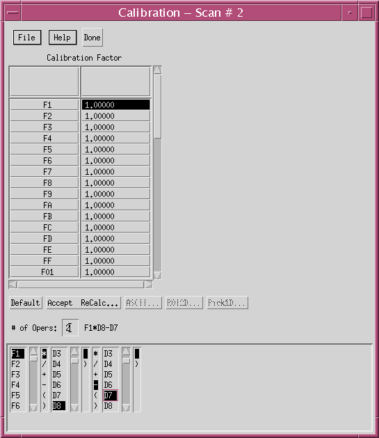
The upper portion of calibration program is the calibration factor control area. It consists of widgets related to the loading, modifying, and saving the definition of calibration factor.
The lower portion consists of widgets related to the calibration function control area. It consists of three rows: a row of calibration function buttons, a row of text field of # of Opers: with resultant calibration function, and a row of scroll area of definition selection lists.
File Menu
    ->Open...        - Load old calibration factor file into table
    ->Save as...     - Store the calibration factor table as a new file
    ->Save           - Replace the opened file by the new calibration
                              factor table
    ->Done           - Close the calibration program
Help...              - Pops up the on-line help about this program
Done                 - Close the calibration program
Table Area           - Enter the new values of calibration factors
The resultant calibration function and the scroll text area containing the selection lists will be updated automatically. Then a user can dynamically re-define the calibration function through selecting the selection lists. The calibration buttons 'Accept & ReCalc...', 'ASCII...' , 'ROI...', and 'Pick1D...' will be activated as soon as the '# of Opers:' is entered.
Default             - Reset all the calibration factors back to 1.0
Accept & ReCalc...  - Accept the calibration function and calculate
                             the new image, then run plot2d program
ASCII...            - Prepare the ASCII file of the calibration 2D
                             image and then run cw_term to display it
ROI2D...            - Run scan2d_roi program with the calibration
                             result
Pick1D...           - Run calibra_pick1d program for accessing
                             various column / row 1D fitting or plotting
# of Opers          - Enter the number of image operations desired
                             followed with the carriage return
Function area       - Display the resultant calibration function
Scroll Lists area   - Select the desired box of lists to re-define the
                             calibration function
The reusltant calibration function is updated whenever the selection lists
or the # of Opers are been modified.
The scroll list area shows the composition of the scroll lists used in the definition of the calibration function. First list is the calibration factor selection box. The # of Opers determines the remaining number of selection boxes of list displayed. For each arithmetic term, there are two lists associated with it: operator selection list and detector selection list.
The calibration factor list consists of NDET factors. The operator list consists of +,-,*,/,(,) selection items. The detector list consists of NDET detector itemes. The NDET is the last detector number defined in scan file.
The constructed function based on the scroll list selections is displayed in the widget of 'Function Area'. A user has to make sure the function is correctly defined before the calculation is performed.
Two types of file can be saved by the calibration program: definition file and report file.