Experimental Physics and
Industrial Control System
| 1994 1995 1996 1997 1998 1999 2000 2001 2002 2003 2004 2005 2006 2007 2008 2009 2010 2011 2012 2013 2014 2015 2016 2017 2018 2019 2020 <2021> 2022 2023 2024 2025 2026 | Index | 1994 1995 1996 1997 1998 1999 2000 2001 2002 2003 2004 2005 2006 2007 2008 2009 2010 2011 2012 2013 2014 2015 2016 2017 2018 2019 2020 <2021> 2022 2023 2024 2025 2026 |
| <== Date ==> | <== Thread ==> |
|---|
| Subject: | modbus write registers error to Pilz PLC |
| From: | 高振华 via Tech-talk <[email protected]> |
| To: | [email protected], [email protected] |
| Date: | Sun, 31 Jan 2021 20:56:33 +0800 (GMT+08:00) |
Hello Mark,
Can Modbus R2-11 be used on the Pilz 4000 PLC?
I am using the PILZ 4000 PLC, but an error exception=2 occurred while debugging Modbus TCP communication.
The IOC has been able to read multiple register (function code 3),
But cannot write to a single register and write to multiple registers(function code 6 and function code 16),Error: exception=2.
Examples of Pilz PLC's command and return value formats are as follows:
(Confirmed with LabVIEW program)
Function code 6:
command: 0000 0000 0006 0106 0000 6262,
Note: 12 bytes in total.
Function code 16: Write three words
command: 0000 0000 000D 0110 0000 0003 0662 6263 6364 64
Note: 19 bytes in total.
PLC(server) read-write register address allocation during test is as follows: (data type:word)
4x0001 to 4x0003 are the write addresses(0x0 to 0x2), (computer writes to the PLC),
4x0004 to 4x0006 are read addresses(0x3 to 0x5), (computer reads from the PLC)
Here is Koyo1.cmd file:
dbLoadDatabase("../../dbd/modbus.dbd")
modbus_registerRecordDeviceDriver(pdbbase)
#drvAsynIPPortConfigure("Koyo1","164.54.160.158:502",0,0,1)
drvAsynIPPortConfigure("Koyo1","192.168.70.40:502",0,0,1)
asynSetOption("Koyo1",0, "disconnectOnReadTimeout", "Y")
modbusInterposeConfig("Koyo1",0,5000,0)
# The DL205 has word access to the Xn inputs at Modbus offset 40400 (octal)
# Read 8 words (128 bits). Function code=3.
#drvModbusAsynConfigure("K1_Xn_Word", "Koyo1", 0, 3, 040400, 010, 0, 100, "Koyo")
drvModbusAsynConfigure("K1_Xn_Word", "Koyo1", 255, 3, 0x3,0x3, 0, 100, "Koyo")
# Write 8 words (128 bits). Function code=6.
#drvModbusAsynConfigure("K1_Yn_Out_Word", "Koyo1", 0, 6, 040500, 010, 0, 100, "Koyo")
drvModbusAsynConfigure("K1_Yn_Out_Word", "Koyo1", 255, 6, 0x0, 0x03, 0, 100, "Koyo")
# We access the same 16 words (C0-C377) as array outputs (256 bits). Function code=16.
#drvModbusAsynConfigure("K1_Cn_Out_Word_Array", "Koyo1", 0, 16, 040600, 020, 0, 1, "Koyo")
drvModbusAsynConfigure("K1_Cn_Out_Word_Array", "Koyo1", 255, 16, 0x0, 0x3, 0, 1, "Koyo")
asynSetTraceIOMask("Koyo1",0,4)
asynSetTraceMask("Koyo1",0,9)
dbLoadTemplate("Koyo1.substitutions")
iocInit
Here is Koyo1.substitutions file:
# These are the Yn outputs done with word access. Y0-Y7
file "../../db/bo_word.template" { pattern
{P, R, PORT, OFFSET, MASK, ZNAM, ONAM}
{KOYO1:, Y0OutW, K1_Yn_Out_Word, 0, 0x0001, Low, High}
{KOYO1:, Y1OutW, K1_Yn_Out_Word, 0, 0x0002, Low, High}
{KOYO1:, Y2OutW, K1_Yn_Out_Word, 0, 0x0004, Low, High}
{KOYO1:, Y3OutW, K1_Yn_Out_Word, 0, 0x0008, Low, High}
{KOYO1:, Y4OutW, K1_Yn_Out_Word, 0, 0x0010, Low, High}
{KOYO1:, Y5OutW, K1_Yn_Out_Word, 0, 0x0020, Low, High}
{KOYO1:, Y6OutW, K1_Yn_Out_Word, 0, 0x0040, Low, High}
{KOYO1:, Y7OutW, K1_Yn_Out_Word, 0, 0x0080, Low, High}
}
file "../../db/intarray_out.template" { pattern
{P, R, PORT, NELM}
{KOYO1:, CnOutWArray, K1_Cn_Out_Word_Array, 3}
}
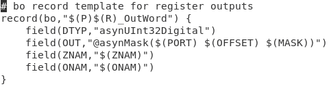
Here is bo_word.template file:
Here is intarray_out.template file:
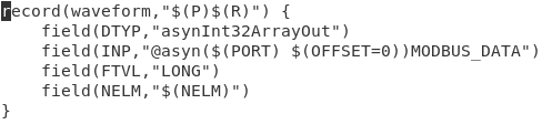
Why is INP here instead of OUT?
drvModbusAsynConfigure function with
function code 6: starting address 0x0, length 0x3.


Please help to see what the reason is?
My application environment:
EPICS
Asyn R4-33
Modbus R2-11
Thanks
Gao Zhenhua
--
BSRF(
Email:[email protected]
- Replies:
- Re: modbus write registers error to Pilz PLC Mark Rivers via Tech-talk
- Navigate by Date:
- Prev: RE: CS-Studio(Phoebus) Archive Viewer Matlab Export Issue Manoussakis, Adamandios via Tech-talk
- Next: Re: modbus write registers error to Pilz PLC Mark Rivers via Tech-talk
- Index: 1994 1995 1996 1997 1998 1999 2000 2001 2002 2003 2004 2005 2006 2007 2008 2009 2010 2011 2012 2013 2014 2015 2016 2017 2018 2019 2020 <2021> 2022 2023 2024 2025 2026
- Navigate by Thread:
- Prev: Problem using PyEpics and pvaPy at the same time on Windows Mark Rivers via Tech-talk
- Next: Re: modbus write registers error to Pilz PLC Mark Rivers via Tech-talk
- Index: 1994 1995 1996 1997 1998 1999 2000 2001 2002 2003 2004 2005 2006 2007 2008 2009 2010 2011 2012 2013 2014 2015 2016 2017 2018 2019 2020 <2021> 2022 2023 2024 2025 2026
· Distributions · Download · Documents · Links · Licensing ·